


Available under Creative Commons-ShareAlike 4.0 International License. Download for free at http://cnx.org/contents/402b20ad-c01f-45f1-9743-05eadb1f710e@37.6
UML class diagrams model static class relationships that represent the fundamental architecture of the system. Note that these diagrams describe the relationships between classes, not those between specific objects instantiated from those classes. Thus the diagram applies to all the objects in the system.
A class diagram consists of the following features:
- Classes: These titled boxes represent the classes in the system and contain information about the name of the class, fields, methods and access specifies. Abstract roles of the class in the system can also be indicated.
- Interfaces: These titled boxes represent interfaces in the system and contain information about the name of the interface and its methods.
-
Relationship Lines that model the relationships between classes and interfaces in the system.
-
Generalization
- Inheritance: a solid line with a solid arrowhead that points from a sub-class to a superclass or from a sub-interface to its super-interface.
- Implementation: a dotted line with a solid arrowhead that points from a class to the interface that it implement
-
Association - a solid line with an open arrowhead that represents a "has a" relationship. The arrow points from the containing to the contained class.
Associations can be one of the following two types or not specified.
- Composition: Represented by an association line with a solid diamond at the tail end. A composition models the notion of one object "owning" another and thus being responsible for the creation and destruction of another object.
- Aggregation: Represented by an association line with a hollow diamond at the tail end. An aggregation models the notion that one object uses another object without "owning" it and thus is not responsible for its creation or destruction.
- Dependency a dotted line with an open arrowhead that shows one entity depends on the behavior of another entity. Typical usages are to represent that one class instantiates another or that it uses the other as an input parameter.
-
Generalization
- Notes that are used to provide further details or explanations of particular parts of the diagram. Notes are boxes with a little "dog-ear" on one corner.
Here is an example of a UML class diagram that holds most of the more common features:
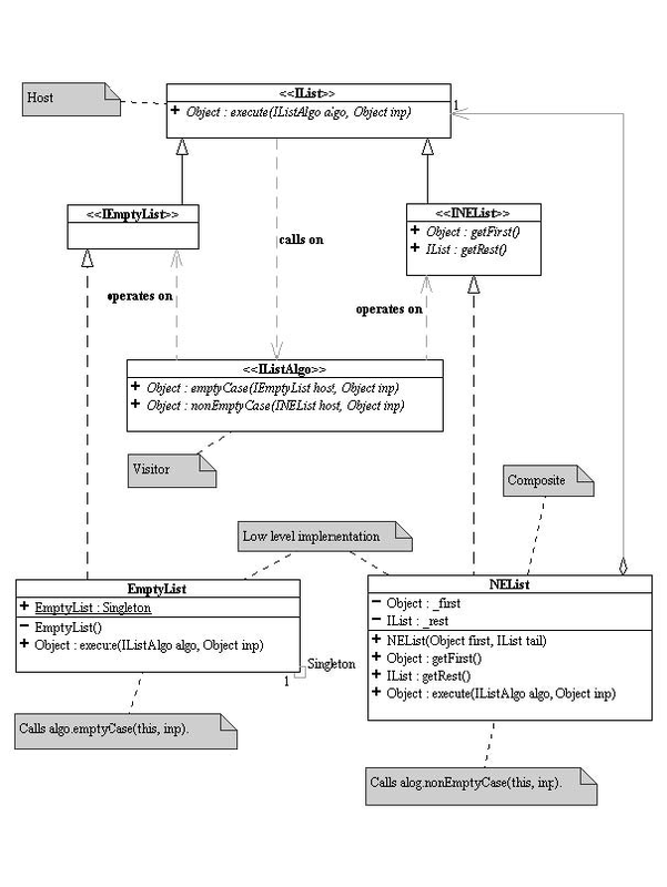
Figure 1.4 UML Class Diagram
The above diagram contains classes, interfaces, inheritance and implementation lines, aggregation lines, dependency lines and notes.
- 瀏覽次數:1579
