


There are two possible internal organisations of the network layer :
- datagram
- virtual circuits
The internal organisation of the network is orthogonal to the service that it provides, but most of the time a datagram organisation is used to provide a connectionless service while a virtual circuit organisation is used in networks that provide a connection-oriented service.
The first and most popular organisation of the network layer is the datagram organisation. This organisation is inspired by the organisation of the postal service. Each host is identified by a network layer address. To send information to a remote host, a host creates a packet that contains :
- the network layer address of the destination host
- its own network layer address
- the information to be sent
The network layer limits the maximum packet size. Thus, the information must have been divided in packets by the transport layer before being passed to the network layer.
To understand the datagram organisation, let us consider the figure below. A network layer address, represented by a letter, has been assigned to each host and router. To send some information to host J, host A creates a packet containing its own address, the destination address and the information to be exchanged.
With the datagram organisation, routers use hop-by-hop forwarding. This means that when a router receives a packet that is not destined to itself, it looks up the destination address of the packet in its routing table. A routing table is a data structure that maps each destination address (or set of destination addresses) to the outgoing interface over which a packet destined to this address must be forwarded to reach its final destination.
The main constraint imposed on the routing tables is that they must allow any host in the network to reach any other host. This implies that each router must know a route towards each destination, but also that the paths composed from the information stored in the routing tables must not contain loops. Otherwise, some destinations would be unreachable.
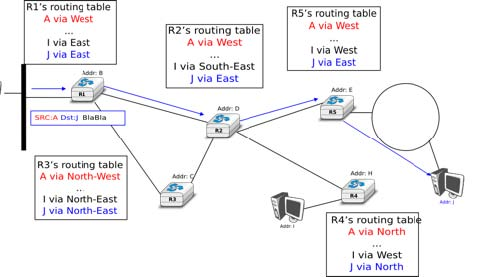
In the example above, host A sends its packet to router R1. R1 consults its routing table and forwards the packet towards R2. Based on its own routing table, R2 decides to forward the packet to R5 that can deliver it to its destination.
To allow hosts to exchange packets, a network relies on two different types of protocols and mechanisms. First, there must be a precise definition of the format of the packets that are sent by hosts and processed by routers. Second, the algorithm used by the routers to forward these packets must be defined. This protocol and this algorithm are part of the data plane of the network layer. The data plane contains all the protocols and algorithms that are used by hosts and routers to create and process the packets that contain user data.
The data plane, and in particular the forwarding algorithm used by the routers, depends on the routing tables that are maintained on reach router. These routing tables can be maintained by using various techniques (manual configuration, distributed protocols, centralised computation, etc). These techniques are part of the control plane of the network layer. The control plane contains all the protocols and mechanisms that are used to compute and install routing tables on the routers.
The datagram organisation has been very popular in computer networks. Datagram based network layers include IPv4 and IPv6 in the global Internet, CLNP defined by the ISO, IPX defined by Novell or XNS defined by Xerox [Perlman2000].
Virtual circuit organisation
The main advantage of the datagram organisation is its simplicity. The principles of this organisation can easily be understood. Furthermore, it allows a host to easily send a packet towards any destination at any time. However, as each packet is forwarded independently by intermediate routers, packets sent by a host may not follow the same path to reach a given destination. This may cause packet reordering, which may be annoying for transport protocols. Furthermore, as a router using hop-by-hop forwarding always forwards packets sent towards the same destination over the same outgoing interface, this may cause congestion over some links.
The second organisation of the network layer, called virtual circuits, has been inspired by the organisation of telephone networks. Telephone networks have been designed to carry phone calls that usually last a few minutes. Each phone is identified by a telephone number and is attached to a telephone switch. To initiate a phone call, a telephone first needs to send the destination’s phone number to its local switch. The switch cooperates with the other switches in the network to create a bi-directional channel between the two telephones through the network. This channel will be used by the two telephones during the lifetime of the call and will be released at the end of the call. Until the 1960s, most of these channels were created manually, by telephone operators, upon request of the caller. Today’s telephone networks use automated switches and allow several channels to be carried over the same physical link, but the principles remain roughly the same.
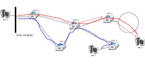
In a network using virtual circuits, all hosts are identified with a network layer address. However, a host must explicitly request the establishment of a virtual circuit before being able to send packets to a destination host. The request to establish a virtual circuit is processed by the control plane, which installs state to create the virtual circuit between the source and the destination through intermediate routers. All the packets that are sent on the virtual circuit contain a virtual circuit identifier that allows the routers to determine to which virtual circuit each packet belongs. This is illustrated in the figure below with one virtual circuit between host A and host I and another one between host A and host J.
The establishment of a virtual circuit is performed using a signalling protocol in the control plane. Usually, the source host sends a signalling message to indicate to its router the address of the destination and possibly some performance characteristics of the virtual circuit to be established. The first router can process the signalling message in two different ways.
A first solution is for the router to consult its routing table, remember the characteristics of the requested virtual circuit and forward it over its outgoing interface towards the destination. The signalling message is thus forwarded hop-by-hop until it reaches the destination and the virtual circuit is opened along the path followed by the signalling message. This is illustrated with the red virtual circuit in the figure below.
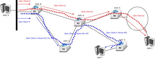
A second solution can be used if the routers know the entire topology of the network. In this case, the first router can use a technique called source routing. Upon reception of the signalling message, the first router chooses the path of the virtual circuit in the network. This path is encoded as the list of the addresses of all intermediate routers to reach the destination. It is included in the signalling message and intermediate routers can remove their address from the signalling message before forwarding it. This technique enables routers to spread the virtual circuits throughout the network better. If the routers know the load of remote links, they can also select the least loaded path when establishing a virtual circuit. This solution is illustrated with the blue circuit in the figure above.
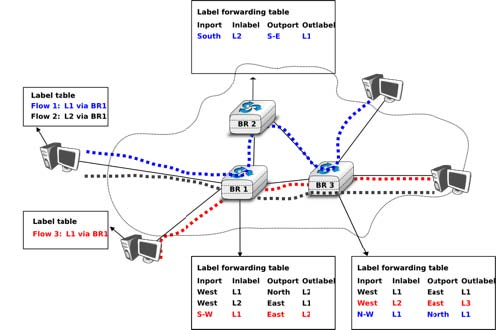
The last point to be discussed about the virtual circuit organisation is its data plane. The data plane mainly defines the format of the data packets and the algorithm used by routers to forward packets. The data packets contain a virtual circuit identifier, encoded as a fixed number of bits. These virtual circuit identifiers are usually called labels.
Each host maintains a flow table that associates a label with each virtual circuit that is has established. When a router receives a packet containing a label, it extracts the label and consults its label forwarding table. This table is a data structure that maps each couple (incoming interface, label) to the outgoing interface to be used to forward the packet as well as the label that must be placed in the outgoing packets. In practice, the label forwarding table can be implemented as a vector and the couple (incoming interface, label) is the index of the entry in the vector that contains the outgoing interface and the outgoing label. Thus a single memory access is sufficient to consult the label forwarding table. The utilisation of the label forwarding table is illustrated in the figure below.
The virtual circuit organisation has been mainly used in public networks, starting from X.25 and then Frame Relay and Asynchronous Transfer Mode (ATM) network.
Both the datagram and virtual circuit organisations have advantages and drawbacks. The main advantage of the datagram organisation is that hosts can easily send packets to any number of destinations while the virtual circuit organisation requires the establishment of a virtual circuit before the transmission of a data packet. This solution can be costly for hosts that exchange small amounts of data. On the other hand, the main advantage of the virtual circuit organisation is that the forwarding algorithm used by routers is simpler than when using the datagram organisation. Furthermore, the utilisation of virtual circuits may allow the load to be better spread through the network thanks to the utilisation of multiple virtual circuits. The MultiProtocol Label Switching (MPLS) technique that we will discuss in another revision of this book can be considered as a good compromise between datagram and virtual circuits. MPLS uses virtual circuits between routers, but does not extend them to the endhosts. Additional information about MPLS may be found in [ML2011].
- 6046 reads
