


As explained earlier, the Internet is composed of more than 30,000 different networks 1 called domains. Each domain is composed of a group of routers and hosts that are managed by the same organisation. Example domains include belnet, sprint, level3, geant, abilene, cisco or google ...
Each domain contains a set of routers. From a routing point of view, these domains can be divided into two classes : the transit and the stub domains. A stub domain sends and receives packets whose source or destination are one of its own hosts. A transit domain is a domain that provides a transit service for other domains, i.e. the routers in this domain forward packets whose source and destination do not belong to the transit domain. As of this writing, about 85% of the domains in the Internet are stub domains. A stub domain that is connected to a single transit domain is called a single-homed stub.A multihomed stub is a stub domain connected to two or more transit providers.
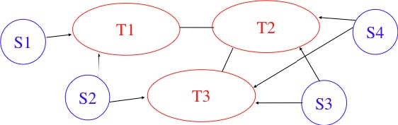
The stub domains can be further classified by considering whether they mainly send or receive packets. An access-rich stub domain is a domain that contains hosts that mainly receive packets. Typical examples include small ADSL-or cable modem-based Internet Service Providers or enterprise networks. On the other hand, a content-rich stub domain is a domain that mainly produces packets. Examples of content-rich stub domains include google, yahoo, microsoft, facebook or content distribution networks such as akamai or limelight For the last few years, we have seen a rapid growth of these content-rich stub domains. Recent measurements [ATLAS2009] indicate that a growing fraction of all the packets exchanged on the Internet are produced in the data centers managed by these content providers.
Domains need to be interconnected to allow a host inside a domain to exchange IP packets with hosts located in other domains. From a physical perspective, domains can be interconnected in two different ways. The first solution is to directly connect a router belonging to the first domain with a router inside the second domain. Such links between domains are called private interdomain links or private peering links. In practice, for redundancy or performance reasons, distinct physical links are usually established between different routers in the two domains that are interconnected.
Such private peering links are useful when, for example, an enterprise or university network needs to be connected to its Internet Service Provider. However, some domains are connected to hundreds of other domains 2. For some of these domains, using only private peering links would be too costly. A better solution to allow many domains to interconnect cheaply are the Internet eXchange Points (IXP). An IXP is usually some space in a data center that hosts routers belonging to different domains. A domain willing to exchange packets with other domains present at the IXP installs one of its routers on the IXP and connects it to other routers inside its own network. The IXP contains a Local Area Network to which all the participating routers are connected. When two domains that are present at the IXP wish 3 to exchange packets, they simply use the Local Area Network. IXPs are very popular in Europe and many Internet Service Providers and Content providers are present in these IXPs.
In the early days of the Internet, domains would simply exchange all the routes they know to allow a host inside one domain to reach any host in the global Internet. However, in today’s highly commercial Internet, this is no longer true as interdomain routing mainly needs to take into account the economical relationships between the domains. Furthermore, while intradomain routing usually prefers some routes over others based on their technical merits (e.g. prefer route with the minimum number of hops, prefer route with the minimum delay, prefer high bandwidth routes over low bandwidth ones, etc) interdomain routing mainly deals with economical issues. For interdomain routing, the cost of using a route is often more important than the quality of the route measured by its delay or bandwidth.
There are different types of economical relationships that can exist between domains. Interdomain routing converts these relationships into peering relationships between domains that are connected via peering links.
The first category of peering relationship is the customer->provider relationship. Such a relationship is used when a customer domain pays an Internet Service Provider to be able to exchange packets with the global Internet over an interdomain link. A similar relationship is used when a small Internet Service Provider pays a larger Internet Service Provider to exchange packets with the global Internet.
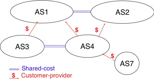
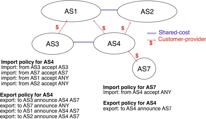
To understand the customer->provider relationship, let us consider the simple internetwork shown in the figure above. In this internetwork, AS7 is a stub domain that is connected to one provider : AS4. The contract between AS4 and AS7 allows a host inside AS7 to exchange packets with any host in the internetwork. To enable this exchange of packets, AS7 must know a route towards any domain and all the domains of the internetwork must know a route via AS4 that allows them to reach hosts inside AS7. From a routing perspective, the commercial contract between AS7 and AS4 leads to the following routes being exchanged :
- over a customer->provider relationship, the customer domain advertises to its provider all its routes and all the routes that it has learned from its own customers.
- over a provider->customer relationship, the provider advertises all the routes that it knows to its customer.
The second rule ensures that the customer domain receives a route towards all destinations that are reachable via its provider. The first rule allows the routes of the customer domain to be distributed throughout the Internet.
Coming back to the figure above, AS4 advertises to its two providers AS1 and AS2 its own routes and the routes learned from its customer, AS7. On the other hand, AS4 advertises to AS7 all the routes that it knows.
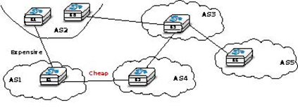
The second type of peering relationship is the shared-cost peering relationship. Such a relationship usually does not involve a payment from one domain to the other in contrast with the customer->provider relationship. A shared-cost peering relationship is usually established between domains having a similar size and geographic coverage. For example, consider the figure above. If AS3 and AS4 exchange many packets via AS1, they both need to pay AS1. A cheaper alternative for AS3 and AS4 would be to establish a shared-cost peering. Such a peering can be established at IXPs where both AS3 and AS4 are present or by using private peering links. This shared-cost peering should be used to exchange packets between hosts inside AS3 and hosts inside AS4. However, AS3 does not want to receive on the AS3-AS4 shared-cost peering links packets whose destination belongs to AS1 as AS3 would have to pay to send these packets to AS1.
From a routing perspective, over a shared-cost peering relationship a domain only advertises its internal routes and the routes that it has learned from its customers. This restriction ensures that only packets destined to the local domain or one of its customers is received over the shared-cost peering relationship. This implies that the routes that have been learned from a provider or from another shared-cost peer is not advertised over a shared-cost peering relationship. This is motivated by economical reasons. If a domain were to advertise the routes that it learned from a provider over a shared-cost peering relationship that does not bring revenue, it would have allowed its shared-cost peer to use the link with its provider without any payment. If a domain were to advertise the routes it learned over a shared cost peering over another shared-cost peering relationship, it would have allowed these shared-cost peers to use its own network (which may span one or more continents) freely to exchange packets.
Finally, the last type of peering relationship is the sibling. Such a relationship is used when two domains exchange all their routes in both directions. In practice, such a relationship is only used between domains that belong to the same company.
These different types of relationships are implemented in the interdomain routing policies defined by each domain. The interdomain routing policy of a domain is composed of three main parts :
- the import filter that specifies, for each peering relationship, the routes that can be accepted from the neighbouring domain (the non-acceptable routes are ignored and the domain never uses them to forward packets)
- the export filter that specifies, for each peering relationship, the routes that can be advertised to the neighbouring domain
- the ranking algorithm that is used to select the best route among all the routes that the domain has received towards the same destination prefix
A domain’s import and export filters can be defined by using the Route Policy Specification Language (RPSL) specified in RFC 2622 [GAVE1999] . Some Internet Service Providers, notably in Europe, use RPSL to document 4 their import and export policies. Several tools help to easily convert a RPSL policy into router commands.
The figure below provides a simple example of import and export filters for two domains in a simple internetwork. In RPSL, the keyword ANY is used to replace any route from any domain. It is typically used by a provider to indicate that it announces all its routes to a customer over a provider->customer relationship. This is the case for AS4‘s export policy. The example below clearly shows the difference between a provider->customer and a shared-cost peering relationship. AS4‘s export filter indicates that it announces only its internal routes (AS4) and the routes learned from its clients (AS7) over its shared-cost peering with AS3, while it advertises all the routes that it uses (including the routes learned from AS3) to AS7.
The Border Gateway Protocol
The Internet uses a single interdomain routing protocol : the Border Gateway Protocol (BGP). The current version of BGP is defined in RFC 4271. BGP differs from the intradomain routing protocols that we have already discussed in several ways. First, BGP is a path-vector protocol. When a BGP router advertises a route towards a prefix, it announces the IP prefix and the interdomain path used to reach this prefix. From BGP’s point of view, each domain is identified by a unique Autonomous System (AS) number 5 and the interdomain path contains the AS numbers of the transit domains that are used to reach the associated prefix. This interdomain path is called the AS Path. Thanks to these AS-Paths, BGP does not suffer from the count-to-infinity problems that affect distance vector routing protocols. Furthermore, the AS-Path can be used to implement some routing policies. Another difference between BGP and the intradomain routing protocols is that a BGP router does not send the entire contents of its routing table to its neighbours regularly. Given the size of the global Internet, routers would be overloaded by the number of BGP messages that they would need to process. BGP uses incremental updates, i.e. it only announces the routes that have changed to its neighbours.
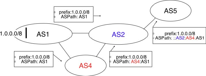
This Figure 5.60 shows a simple example of the BGP routes that are exchanged between domains. In this example, prefix 1.0.0.0/8 is announced by AS1. AS1 advertises a BGP route towards this prefix to AS2. The AS-Path of this route indicates that AS1 is the originator of the prefix. When AS4 receives the BGP route from AS1, it re-announces it to AS2 and adds its AS number to the AS-Path. AS2 has learned two routes towards prefix 1.0.0.0/8. It compares the two routes and prefers the route learned from AS4 based on its own ranking algorithm. AS2 advertises to AS5 a route towards 1.0.0.0/8 with its AS-Path set to AS2:AS4:AS1. Thanks to the AS-Path, AS5 knows that if it sends a packet towards 1.0.0.0/8 the packet first passes through AS2, then through AS4 before reaching its destination inside AS1.
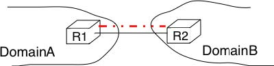
BGP routers exchange routes over BGP sessions. A BGP session is established between two routers belonging to two different domains that are directly connected. As explained earlier, the physical connection between the two routers can be implemented as a private peering link or over an Internet eXchange Point. A BGP session between two adjacent routers runs above a TCP connection (the default BGP port is 179). In contrast with intradomain routing protocols that exchange IP packets or UDP segments, BGP runs above TCP because TCP ensures a reliable delivery of the BGP messages sent by each router without forcing the routers to implement acknowledgements, checksums, etc. Furthermore, the two routers consider the peering link to be up as long as the BGP session and the underlying TCP connection remain up 6. The two endpoints of a BGP session are called BGP peers.

In practice, to establish a BGP session between routers R1 and R2 in the figure above, the network administrator of AS3 must first configure on R1 the IP address of R2 on the R1-R2 link and the AS number of R2. Router R1 then regularly tries to establish the BGP session with R2. R2 only agrees to establish the BGP session with R1 once it has been configured with the IP address of R1 and its AS number. For security reasons, a router never establishes a BGP session that has not been manually configured on the router.
The BGP protocol RFC 4271 defines several types of messages that can be exchanged over a BGP session :
- OPEN : this message is sent as soon as the TCP connection between the two routers has been established. It initialises the BGP session and allows the negotiation of some options. Details about this message may be found in RFC 4271
- NOTIFICATION : this message is used to terminate a BGP session, usually because an error has been detected by the BGP peer. A router that sends or receives a NOTIFICATION message immediately shutdowns the corresponding BGP session.
- UPDATE: this message is used to advertise new or modified routes or to withdraw previously advertised routes.
- KEEPALIVE : this message is used to ensure a regular exchange of messages on the BGP session, even when no route changes. When a BGP router has not sent an UPDATE message during the last 30 seconds, it shall send a KEEPALIVE message to confirm to the other peer that it is still up. If a peer does not receive any BGP message during a period of 90 seconds 7, the BGP session is considered to be down and all the routes learned over this session are withdrawn.
As explained earlier, BGP relies on incremental updates. This implies that when a BGP session starts, each router first sends BGP UPDATE messages to advertise to the other peer all the exportable routes that it knows. Once all these routes have been advertised, the BGP router only sends BGP UPDATE messages about a prefix if the route is new, one of its attributes has changed or the route became unreachable and must be withdrawn. The BGP UPDATE message allows BGP routers to efficiently exchange such information while minimising the number of bytes exchanged. Each UPDATE message contains :
- a list of IP prefixes that are withdrawn
- a list of IP prefixes that are (re-)advertised
- the set of attributes (e.g. AS-Path) associated to the advertised prefixes
In the remainder of this chapter, and although all routing information is exchanged using BGP UPDATE messages, we assume for simplicity that a BGP message contains only information about one prefix and we use the words :
- Withdraw message to indicate a BGP UPDATE message containing one route that is withdrawn
- Update message to indicate a BGP UPDATE containing a new or updated route towards one destination prefix with its attributes needs to be rebooted
From a conceptual point of view, a BGP router connected to N BGP peers, can be described as being composed of four parts as shown in the figure below.
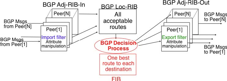
In this figure, the router receives BGP messages on the left part of the figure, processes these messages and possibly sends BGP messages on the right part of the figure. A BGP router contains three important data structures :
- the Adj-RIB-In contains the BGP routes that have been received from each BGP peer. The routes in the Adj-RIB-In are filtered by the import filter before being placed in the BGP-Loc-RIB. There is one import filter per BGP peer.
- the Local Routing Information Base (Loc-RIB) contains all the routes that are considered as acceptable by the router. The Loc-RIB may contain several routes, learned from different BGP peers, towards the same destination prefix.
- the Forwarding Information Base (FIB) is used by the dataplane to forward packets towards their destination. The FIB contains, for each destination, the best route that has been selected by the BGP decision process. This decision process is an algorithm that selects, for each destination prefix, the best route according to the router’s ranking algorithm that is part of its policy.
- the Adj-RIB-Out contains the BGP routes that have been advertised to each BGP peer. The Adj-RIB-Out for a given peer is built by applying the peer‘s export filter on the routes that have been installed in the FIB. There is one export filter per BGP peer. For this reason, the Adj-RIB-Out of a peer may contain different routes than the Adj-RIB-Out of another peer.
When a BGP session starts, the routers first exchange OPEN messages to negotiate the options that apply throughout the entire session. Then, each router extracts from its FIB the routes to be advertised to the peer. It is important to note that, for each known destination prefix, a BGP router can only advertise to a peer the route that it has itself installed inside its FIB. The routes that are advertised to a peer must pass the peer’s export filter. The export filter is a set of rules that define which routes can be advertised over the corresponding session, possibly after having modified some of its attributes. One export filter is associated to each BGP session. For example, on a shared-cost peering, the export filter only selects the internal routes and the routes that have been learned from a customer. The pseudo-code below shows the initialisation of a BGP session.
def initiliaze_BGP_session( RemoteAS, RemoteIP): # Initialize and start BGP session # Send BGP OPEN Message to RemoteIP on port 179 # Follow BGP state machine # advertise local routes and routes learned from peers*/ for d in BGPLocRIB : B=build_BGP_Update(d) S=Apply_Export_Filter(RemoteAS,B) if (S != None) : send_Update(S,RemoteAS,RemoteIP) # entire RIB has been sent # new Updates will be sent to reflect local or distant # changes in routers
In the above pseudo-code, the build_BGP_UPDATE(d) procedure extracts from the BGP Loc-RIB the best path towards destination d (i.e. the route installed in the FIB) and prepares the corresponding BGP UPDATE message.
This message is then passed to the export filter that returns NULL if the route cannot be advertised to the peer or the (possibly modified) BGP UPDATE message to be advertised. BGP routers allow network administrators to specify very complex export filters, see e.g. [WMS2004]. A simple export filter that implements the equivalent of split horizon is shown below.
def apply_export_filter(RemoteAS, BGPMsg) :   # check if RemoteAS already received route   if RemoteAS is BGPMsg.ASPath : BGPMsg=None       # Many additional export policies can be configured :
      # Accept or refuse the BGPMsg
      # Modify selected attributes inside BGPMsg return BGPMsg
At this point, the remote router has received all the exportable BGP routes. After this initial exchange, the router only sends BGP UPDATE messages when there is a change (addition of a route, removal of a route or change in the attributes of a route) in one of these exportable routes. Such a change can happen when the router receives a BGP message. The pseudo-code below summarizes the processing of these BGP messages.
def Recvd_BGPMsg(Msg, RemoteAS) :     B=apply_import_filer(Msg,RemoteAS)     if (B== None): # Msg not acceptable       return     if IsUPDATE(Msg):       Old_Route=BestRoute(Msg.prefix)       Insert_in_RIB(Msg)       Run_Decision_Process(RIB)       if (BestRoute(Msg.prefix) != Old_Route) :         # best route changed         B=build_BGP_Message(Msg.prefix);         S=apply_export_filter(RemoteAS,B);         if (S!=None) : # announce best route           send_UPDATE(S,RemoteAS,RemoteIP);         else if (Old_Route != None) :           send_WITHDRAW(Msg.prefix,RemoteAS, RemoteIP)     else : # Msg is WITHDRAW       Old_Route=BestRoute(Msg.prefix)       Remove_from_RIB(Msg)       Run_Decision_Process(RIB)       if (Best_Route(Msg.prefix) !=Old_Route):         # best route changed         B=build_BGP_Message(Msg.prefix)         S=apply_export_filter(RemoteAS,B)         if (S != None) : # still one best route towards Msg.prefix           send_UPDATE(S,RemoteAS, RemoteIP);         else if(Old_Route != None) : # No best route anymore
          send_WITHDRAW(Msg.prefix,RemoteAS,RemoteIP);
When a BGP message is received, the router first applies the peer’s import filter to verify whether the message is acceptable or not. If the message is not acceptable, the processing stops. The pseudo-code below shows a simple import filter. This import filter accepts all routes, except those that already contain the local AS in their AS-Path. If such a route was used, it would cause a routing loop. Another example of an import filter would be a filter used by an Internet Service Provider on a session with a customer to only accept routes towards the IP prefixes assigned to the customer by the provider. On real routers, import filters can be much more complex and some import filters modify the attributes of the received BGP UPDATE [WMS2004] .
def apply_import_filter (RemoteAS, BGMsg) if MysAS in BGPMsg.ASPath : BGPMsg=None # Many additional import policies can be configured : # Accept or refuse the BGPMsg # Modify selected attributes inside BGPMsg return BGPMsg
Another example of frequently used import filters are the filters that Internet Service Providers use to ignore bogon routes. In the ISP community, a bogon route is a route that should not be advertised on the global Internet. Typical examples include the private IPv4 prefixes defined in RFC 1918, the loopback prefixes (127.0.0.1/8 and ::1/128) or the IP prefixes that have not yet been allocated by IANA. A well managed BGP router should ensure that it never advertises bogons on the global Internet. Detailed information about these bogons may be found here.
If the import filter accepts the BGP message, the pseudo-code distinguishes two cases. If this is an Update message for prefix p, this can be a new route for this prefix or a modification of the route’s attributes. The router first retrieves from its RIB the best route towards prefix p. Then, the new route is inserted in the RIB and the BGP decision process is run to find whether the best route towards destination p changes. A BGP message only needs to be sent to the router’s peers if the best route has changed. For each peer, the router applies the export filter to verify whether the route can be advertised. If yes, the filtered BGP message is sent. Otherwise, a Withdraw message is sent. When the router receives a Withdraw message, it also verifies whether the removal of the route from its RIB caused its best route towards this prefix to change. It should be noted that, depending on the content of the RIB and the export filters, a BGP router may need to send a Withdraw message to a peer after having received an Update message from another peer and conversely.
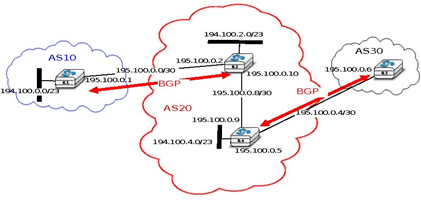
Let us now discuss in more detail the operation of BGP in an IPv4 network. For this, let us consider the simple network composed of three routers located in three different ASes and shown in the figure below.
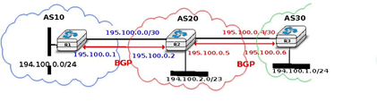
This network contains three routers : R1, R2 and R3. Each router is attached to a local IPv4 subnet that it advertises using BGP. There are two BGP sessions, one between R1 and R2 and the second between R2 and R3.A /30 subnet is used on each interdomain link (195.100.0.0/30 on R1-R2 and 195.100.0.4/30 on R2-R3). The BGP sessions run above TCP connections established between the neighbouring routers (e.g. 195.100.0.1 -195.100.0.2 for the R1-R2 session).
Let us assume that the R1-R2 BGP session is the first to be established. A BGP Update message sent on such a session contains three fields :
- the advertised prefix
- the BGP nexthop
- the attributes including the AS-Path
We use the notation U(prefix, nexthop, attributes) to represent such a BGP Update message in this section. Similarly, W(prefix) represents a BGP withdraw for the specified prefix. Once the R1-R2 session has been established, R1 sends U(194.100.0.0/24,195.100.0.1,AS10) to R2 and R2 sends U(194.100.2.0/23,195.100.0.2,AS20). At this point, R1 can reach 194.100.2.0/23 via 195.100.0.2 and R2 can reach 194.100.0.0/24 via 195.100.0.1.
Once the R2-R3 has been established, R3 sends U (194.100.1.0/24,195.100.0.6,AS30). R2 announces on the R2R3 session all the routes inside its RIB. It thus sends to R3 : U(194.100.0.0/24,195.100.0.5,AS20:AS10) and U(194.100.2.0/23,195.100.0.5,AS20). Note that when R2 advertises the route that it learned from R1, it updates the BGP nexthop and adds its AS number to the AS-Path. R2 also sends U(194.100.1.0/24,195.100.0.2,AS20:AS30) to R1 on the R1-R3 session. At this point, all BGP routes have been exchanged and all routers can reach 194.100.0.0/24, 194.100.2.0/23 and 194.100.1.0/24.
If the link between R2 and R3 fails, R3 detects the failure as it did not receive KEEPALIVE messages recently from R2. At this time, R3 removes from its RIB all the routes learned over the R2-R3 BGP session. R2 also removes from its RIB the routes learned from R3. R2 also sends W(194.100.1.0/24) to R1 over the R1-R3 BGP session since it does not have a route anymore towards this prefix.
A frequent practical question about the operation of BGP is how a BGP router decides to originate or advertise a route for the first time. In practice, this occurs in two situations :
- the router has been manually configured by the network operator to always advertise one or several routes on a BGP session. For example, on the BGP session between UCLouvain and its provider, belnet , UCLouvain’s router always advertises the 130.104.0.0/16 IPv4 prefix assigned to the campus network
- the router has been configured by the network operator to advertise over its BGP session some of the routes that it learns with its intradomain routing protocol. For example, an enterprise router may advertise over a BGP session with its provider the routes to remote sites when these routes are reachable and advertised by the intradomain routing protocol
The first solution is the most frequent. Advertising routes learned from an intradomain routing protocol is not recommended, this is because if the route flaps 8, this would cause a large number of BGP messages being exchanged in the global Internet.
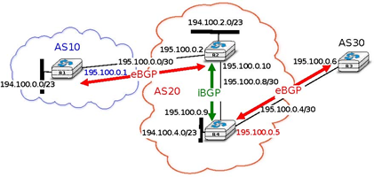
Most networks that use BGP contain more than one router. For example, consider the network shown in the figure below where AS20 contains two routers attached to interdomain links : R2 and R4. In this network, two routing protocols are used by R2 and R4. They use an intradomain routing protocol such as OSPF to distribute the routes towards the internal prefixes : 195.100.0.8/30, 195.100.0.0/30, ... R2 and R4 also use BGP. R2 receives the routes advertised by AS10 while R4 receives the routes advertised by AS30. These two routers need to exchange the routes that they have respectively received over their BGP sessions.
A first solution to allow R2 and R3 to exchange the interdomain routes that they have learned over their respective BGP sessions would be to configure the intradomain routing protocol to distribute inside AS20 the routes learned over the BGP sessions. Although current routers support this feature, this is a bad solution for two reasons :
- Intradomain routing protocols cannot distribute the attributes that are attached to a BGP route. If R4 received via the intradomain routing protocol a route towards 194.100.0.0/23 that R2 learned via BGP, it would not know that the route was originated by AS10 and the only advertisement that it could send to R3 would contain an incorrect AS-Path
- Intradomain routing protocols have not been designed to support the hundreds of thousands of routes that a BGP router can receive on today’s global Internet.
The best solution to allow BGP routers to distribute, inside an AS, all the routes learned over BGP sessions is to establish BGP sessions among all the BGP routers inside the AS. In practice, there are two types of BGP sessions :
- eBGP session or external BGP session. Such a BGP session is established between two routers that are directly connected and belong to two different domains.
- iBGP session or internal BGP session. Such a BGP session is established between two routers belonging to the same domain. These two routers do not need to be directly connected.
In practice, each BGP router inside a domain maintains an iBGP session with every other BGP router in the domain 9. This creates a full-mesh of iBGP sessions among all BGP routers of the domain. iBGP sessions, like eBGP sessions run over TCP connections. Note that in contrast with eBGP sessions that are established between directly connected routers, iBGP sessions are often established between routers that are not directly connected.
An important point to note about iBGP sessions is that a BGP router only advertises a route over an iBGP session provided that :
- the router uses this route to forward packets, and
- the route was learned over one of the router’s eBGP sessions
A BGP router does not advertise a route that it has learned over an iBGP session over another iBGP session. Note that a router can, of course, advertise over an eBGP session a route that it has learned over an iBGP session. This difference between the behaviour of a BGP router over iBGP and eBGP session is due to the utilisation of a full-mesh of iBGP sessions. Consider a network containing three BGP routers : A, B and C interconnected via a full-mesh of iBGP sessions. If router A learns a route towards prefix p from router B, router A does not need to advertise the received route to router C since router C also learns the same route over the C-B iBGP session.
To understand the utilisation of an iBGP session, let us consider what happens when router R1 sends U(194.100.0.0/23,195.100.0.1,AS10) in the network shown below. This BGP message is processed by R2 which advertises it over its iBGP session with R4. The BGP Update sent by R2 contains the same nexthop and the same AS-Path as in the BGP Update received by R2. R4 then sends U(194.100.0.0/23,195.100.0.5,AS20:AS10) to R3. Note that the BGP nexthop and the AS-Path are only updated 10 when a BGP route is advertised over an eBGP session.
In addition to their physical interfaces, routers can also be configured with a special loopback interface. A loop-back interface is a software interface that is always up. When a loopback interface is configured on a router, the address associated to this interface is advertised by the intradomain routing protocol. Consider for example a router with two point-to-point interfaces and one loopback interface. When a point-to-point interface fails, it becomes unreachable and the router cannot receive anymore packets via this IP address. This is not the case for the loopback interface. It remains reachable as long as at least one of the router’s interfaces remains up. iBGP sessions are usually established using the router’s loopback addresses as endpoints. This allows the iBGP session and its underlying TCP connection to remain up even if physical interfaces fail on the routers.
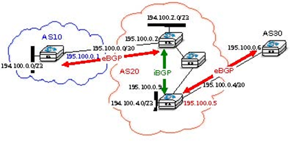
Now that routers can learn interdomain routes over iBGP and eBGP sessions, let us examine what happens when router R3 sends a packet destined to 194.100.1.234. R3 forwards this packet to R4. R4 uses an intradomain routing protocol and BGP. Its BGP routing table contains the following longest prefix match :
- 194.100.0.0/23 via 195.100.0.1
This routes indicates that to forward a packet towards 194.100.0.0/23, R4 needs to forward the packet along the route towards 195.100.0.1. However, R4 is not directly connected to 195.100.0.1. R4 learned a route that matches this address thanks to its intradomain routing protocol that distributed the following routes :
- 195.100.0.0/30 via 195.100.0.10
- 195.100.0.4/30 East
- 195.100.0.8/30 North
- 194.100.2.0/23 via 195.100.0.10
- 194.100.0.4/23 West
To build its forwarding table, R4 must combine the routes learned from the intradomain routing protocol with the routes learned from BGP. Thanks to its intradomain routing table, for each interdomain route R4 replaces the BGP nexthop with its shortest path computed by the intradomain routing protocol. In the figure above, R4 forwards packets to 194.100.0.0/23 via 195.100.0.10 to which it is directly connected via its North interface. R4 ‘s resulting forwarding table, which associates an outgoing interface for a directly connected prefix or a directly connected nexthop and an outgoing interface for prefixes learned via BGP, is shown below :
- 194.100.0.0/23 via 195.100.0.10 (North)
- 195.100.0.0/30 via 195.100.0.10 (North)
- 195.100.0.4/30 East
- 195.100.0.8/30 North
- 194.100.2.0/23 via 195.100.0.10 (North)
- 194.100.4.0/23 West
There is thus a coupling between the interdomain and the intradomain routing tables. If the intradomain routes change, e.g. due to link failures or changes in link metrics, then the forwarding table must be updated on each router as the shortest path towards a BGP nexthop may have changed.
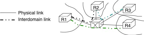
The last point to be discussed before looking at the BGP decision process is that a network may contain routers that do not maintain any eBGP session. These routers can be stub routers attached to a single router in the network or core routers that reside on the path between two border routers that are using BGP as illustrated in the figure below.
In the scenario above, router R2 needs to be able to forward a packet towards any destination in the 12.0.0.0/8 prefix inside AS30. Such a packet would need to be forwarded by router R5 since this router resides on the path between R2 and its BGP nexthop attached to R4. Two solutions can be used to ensure that R2 is able to forward such interdomain packets :
- enable BGP on router R5 and include this router in the iBGP full-mesh. Two iBGP sessions would be added in the figure above : R2-R5 and R4-R5. This solution works and is used by many ASes. However, it forces all routers to have enough resources (CPU and memory) to run BGP and maintain a large forwarding table
- encapsulate the interdomain packets sent through the AS so that router R5 never needs to forward a packet whose destination is outside the local AS. Different encapsulation mechanisms exist. MultiProtocol Label Switching (MPLS) RFC 3031 and the Layer 2 Tunneling Protocol (L2TP) RFC 3931 are frequently used in large domains, but a detailed explanation of these techniques is outside the scope of this section. The simplest encapsulation scheme to understand is in IP in IP defined in RFC 2003. This encapsulation scheme places an IP packet (called the inner packet), including its payload, as the payload of a larger IP packet (called the outer packet). It can be used by border routers to forward packets via routers that do not maintain a BGP routing table. For example, in the figure above, if router R2 needs to forward a packet towards destination 12.0.0.1, it can add at the front of this packet an IPv4 header whose source address is set to one of its IPv4 addresses and whose destination address is one of the IPv4 addresses of R4. The Protocol field of the IP header is set to 4 to indicate that it contains an IPv4 packet. The packet is forwarded by R5 to R4 based on the forwarding table that it built thanks to its intradomain routing table. Upon reception of the packet, R4 removes the outer header and consults its (BGP) forwarding table to forward the packet towards R3.
The BGP decision process
Besides the import and export filters, a key difference between BGP and the intradomain routing protocols is that each domain can define is own ranking algorithm to determine which route is chosen to forward packets when several routes have been learned towards the same prefix. This ranking depends on several BGP attributes that can be attached to a BGP route.
The first BGP attribute that is used to rank BGP routes is the local-preference (local-pref) attribute. This attribute is an unsigned integer that is attached to each BGP route received over an eBGP session by the associated import filter.
When comparing routes towards the same destination prefix, a BGP router always prefers the routes with the highest local-pref. If the BGP router knows several routes with the same local-pref, it prefers among the routes having this local-pref the ones with the shortest AS-Path.
The local-pref attribute is often used to prefer some routes over others. This attribute is always present inside BGP Updates exchanged over iBGP sessions, but never present in the messages exchanged over eBGP sessions.
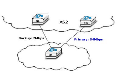
A common utilisation of local-pref is to support backup links. Consider the situation depicted in the figure below. AS1 would always like to use the high bandwidth link to send and receive packets via AS2 and only use the backup link upon failure of the primary one.
As BGP routers always prefer the routes with the highest local-pref attribute, this policy can be implemented using the following import filter on R1
import: from AS2 RA at R1 set localpref=100; from AS2 RB at R1 set localpref=200; accept ANY
With this import filter, all the BGP routes learned from RB over the high bandwidth links are preferred over the routes learned over the backup link. If the primary link fails, the corresponding routes are removed from R1‘s RIB and R1 uses the route learned from RA. R1 reuses the routes via RB as soon as they are advertised by RB once the R1-RB link comes back.
The import filter above modifies the selection of the BGP routes inside AS1. Thus, it influences the route followed by the packets forwarded by AS1. In addition to using the primary link to send packets, AS1 would like to receive its packets via the high bandwidth link. For this, AS2 also needs to set the local-pref attribute in its import filter.
import: from AS1 R1 at RA set localpref=100; from AS1 R1 at RB set localpref=200; accept AS1
Sometimes, the local-pref attribute is used to prefer a cheap link compared to a more expensive one. For example, in the network below, AS1 could wish to send and receive packets mainly via its interdomain link with AS4.
AS1 can install the following import filter on R1 to ensure that it always sends packets via R2 when it has learned a route via AS2 and another via AS4.
import: from AS2 RA at R1 set localpref=100; from AS4 R2 at R1 set localpref=200; accept ANY
However, this import filter does not influence how AS3 , for example, prefers some routes over others. If the link between AS3 and AS2 is less expensive than the link between AS3 and AS4, AS3 could send all its packets via AS2 and AS1 would receive packets over its expensive link. An important point to remember about local-pref is that it can be used to prefer some routes over others to send packets, but it has no influence on the routes followed by received packets.
Another important utilisation of the local-pref attribute is to support the customer->provider and shared-cost peering relationships. From an economic point of view, there is an important difference between these three types of peering relationships. A domain usually earns money when it sends packets over a provider->customer relationship. On the other hand, it must pay its provider when it sends packets over a customer->provider relationship.
Using a shared-cost peering to send packets is usually neutral from an economic perspective. To take into account these economic issues, domains usually configure the import filters on their routers as follows :
- insert a high local-pref attribute in the routes learned from a customer
- insert a medium local-pref attribute in the routes learned over a shared-cost peering
- insert a low local-pref attribute in the routes learned from a provider
With such an import filter, the routers of a domain always prefer to reach destinations via their customers whenever such a route exists. Otherwise, they prefer to use shared-cost peering relationships and they only send packets via their providers when they do not know any alternate route. A consequence of setting the local-pref attribute like this is that Internet paths are often asymmetrical. Consider for example the internetwork shown in the figure below.
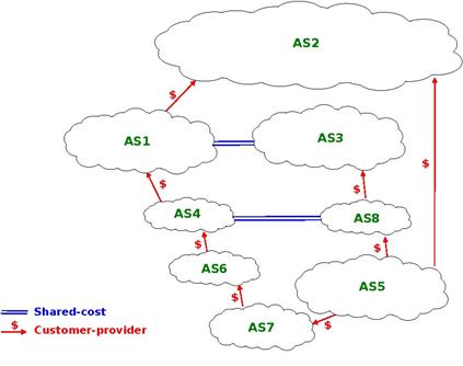
Consider in this internetwork the routes available inside AS1 to reach AS5. AS1 learns the AS4:AS6:AS7:AS5 path from AS4, the AS3:AS8:AS5 path from AS3 and the AS2:AS5 path from AS2. The first path is chosen since it was from learned from a customer. AS5 on the other hand receives three paths towards AS1 via its providers. It may select any of these paths to reach AS1 , depending on how it prefers one provider over the others.
Coming back to the organisation of a BGP router shown in figure Figure 5.62, the last part to be discussed is the BGP decision process. The BGP Decision Process is the algorithm used by routers to select the route to be installed in the FIB when there are multiple routes towards the same prefix. The BGP decision process receives a set of candidate routes towards the same prefix and uses seven steps. At each step, some routes are removed from the candidate set and the process stops when the set only contains one route 11:
- Ignore routes having an unreachable BGP nexthop
- Prefer routes having the highest local-pref
- Prefer routes having the shortest AS-Path
- Prefer routes having the smallest MED
- Prefer routes learned via eBGP sessions over routes learned via iBGP sessions
- Prefer routes having the closest next-hop
- Tie breaking rules : prefer routes learned from the router with lowest router id
The first step of the BGP decision process ensures that a BGP router does not install in its FIB a route whose nexthop is considered to be unreachable by the intradomain routing protocol. This could happen, for example, when a router has crashed. The intradomain routing protocol usually advertises the failure of this router before the failure of the BGP sessions that it terminates. This rule implies that the BGP decision process must be re-run each time the intradomain routing protocol reports a change in the reachability of a prefix containing one of more BGP nexthops.
The second rule allows each domain to define its routing preferences. The local-pref attribute is set by the import filter of the router that learned a route over an eBGP session.
In contrast with intradomain routing protocols, BGP does not contain an explicit metric. This is because in the global Internet it is impossible for all domains to agree on a common metric that meets the requirements of all domains. Despite this, BGP routers prefer routes having a short AS-Path attribute over routes with a long AS-Path. This step of the BGP decision process is motivated by the fact that operators expect that a route with a long AS-Path is lower quality than a route with a shorter AS-Path. However, studies have shown that there was not always a strong correlation between the quality of a route and the length of its AS-Path [HFPMC2002].
Before explaining the fourth step of the BGP decision process, let us first describe the fifth and the sixth steps of the BGP decision process. These two steps are used to implement hot potato routing. Intuitively, when a domain implements hot potato routing, it tries to forward packets that are destined to addresses outside of its domain, to other domains as quickly as possible.
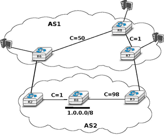
To understand hot potato routing, let us consider the two domains shown in the figure below. AS2 advertises prefix 1.0.0.0/8 over the R2-R6 and R3-R7 peering links. The routers inside AS1 learn two routes towards 1.0.0.0/8: one via R6-R2 and the second via R7-R3.
With the fifth step of the BGP decision process, a router always prefers to use a route learned over an eBGP session compared to a route learned over an iBGP session. Thus, router R6 (resp. R7) prefers to use the route via router R2 (resp. R3) to reach prefix 1.0.0.0/8.
The sixth step of the BGP decision process takes into account the distance, measured as the length of the shortest intradomain path, between a BGP router and the BGP nexthop for routes learned over iBGP sessions. This rule is used on router R8 in the example above. This router has received two routes towards 1.0.0.0/8:
- 1.0.0.0/8 via R7 that is at a distance of 1 from R8
- 1.0.0.0/8 via R6 that is at a distance of 50 from R8
The first route, via R7 is the one that router R8 prefers, as this is the route that minimises the cost of forwarding packets inside AS1 before sending them to AS2.
Hot potato routing allows AS1 to minimise the cost of forwarding packets towards AS2. However, there are situations where this is not desirable. For example, assume that AS1 and AS2 are domains with routers on both the East and the West coast of the US. In these two domains, the high metric associated to links R6-R8 and R0-R2 correspond to the cost of forwarding a packet across the USA. If AS2 is a customer that pays AS1, it would prefer to receive the packets destined to 1.0.0.0/8 via the R2-R6 link instead of the R7-R3 link. This is the objective of cold potato routing.
Cold potato routing is implemented using the Multi-Exit Discriminator (MED) attribute. This attribute is an optional BGP attribute that may be set 12 by border routers when advertising a BGP route over an eBGP session. The MED attribute is usually used to indicate over an eBGP session the cost to reach the BGP nexthop for the advertised route. The MED attribute is set by the router that advertises a route over an eBGP session. In the example above, router R2 sends U(1.0.0.0/8,R2,AS2,MED=1) while R3 sends U(1.0.0.0/8,R3,AS2,MED=98).
Assume that the BGP session R7-3 is the first to be established. R7 sends U(1.0.0.0/8,R3,AS2,MED=98) to both R8 and R6. At this point, all routers inside AS1 send the packets towards 1.0.0.0/8 via R7-R3. Then, the R6R2 BGP session is established and router R6 receives U(1.0.0.0/8,R2,AS2,MED=1). Router R6 runs its decision process for destination 1.0.0.0/8 and selects the route via R2 as its chosen route to reach this prefix since this is the only route that it knows. R6 sends U(1.0.0.0/8,R2,AS2,MED=1) to routers R8 and R7. They both run their decision process and prefer the route advertised by R6, as it contains the smallest MED. Now, all routers inside AS1 forward the packets to 1.0.0.0/8 via link R6-R2 as expected by AS2. As router R7 no longer uses the BGP route learned via R3, it must stop advertising it over iBGP sessions and sends W(1.0.0.0/8) over its iBGP sessions with R6 and R8. However, router R7 still keeps the route learned from R3 inside its Adj-RIB-In. If the R6-R2 link fails, R6 sends W(1.0.0.0/8) over its iBGP sessions and router R7 responds by sending U(1.0.0.0/8,R3,AS2,MED=98) over its iBGP sessions.
In practice, the fifth step of the BGP decision process is slightly more complex, as the routes towards a given prefix can be learned from different ASes. For example, assume that in figure Hot and cold potato routing, 1.0.0.0/8 is also advertised by AS3 (not shown in the figure) that has peering links with routers R6 and R8. If AS3 advertises a route whose MED attribute is set to 2 and another with a MED set to 3, how should AS1‘s router compare the four BGP routes towards 1.0.0.0/8 ? Is a MED value of 1 from AS2 better than a MED value of 2 from AS3 ? The fifth step of the BGP decision process solves this problem by only comparing the MED attribute of the routes learned from the same neighbour AS. Additional details about the MED attribute may be found in RFC 4451. It should be noted that using the MED attribute may cause some problems in BGP networks as explained in [GW2002]. In practice, the MED attribute is not used on eBGP sessions unless the two domains agree to enable it.
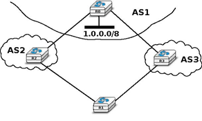
The last step of the BGP decision allows the selection of a single route when a BGP router has received several routes that are considered as equal by the first six steps of the decision process. This can happen for example in a dual-homed stub attached to two different providers. As shown in the figure below, router R1 receives two equally good BGP routes towards 1.0.0.0/8. To break the ties, each router is identified by a unique router-id which in practice is one of the IP addresses assigned to the router. On some routers, the lowest router id step in the BGP decision process is replaced by the selection of the oldest route RFC 5004. Preferring the oldest route when breaking ties is used to prefer stable paths over unstable paths. However, a drawback of this approach is that the selection of the BGP routes depends on the arrival times of the corresponding messages. This makes the BGP selection process non-deterministic and can lead to problems that are difficult to debug.
BGP convergence
In the previous sections, we have explained the operation of BGP routers. Compared to intradomain routing protocols, a key feature of BGP is its ability to support interdomain routing policies that are defined by each domain as its import and export filters and ranking process. A domain can define its own routing policies and router vendors have implemented many configuration tweaks to support complex routing policies. However, the routing policy chosen by a domain may interfere with the routing policy chosen by another domain. To understand this issue, let us first consider the simple internetwork shown below.
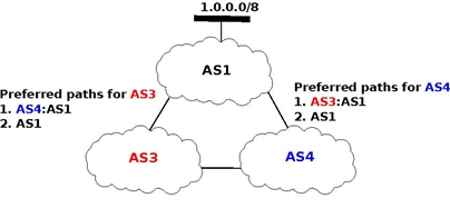
In this internetwork, we focus on the route towards 1.0.0.0/8 which is advertised by AS1. Let us also assume that AS3 (resp. AS4) prefers, e.g. for economic reasons, a route learned from AS4 (AS3) over a route learned from AS1. When AS1 sends U(1.0.0.0/8,AS1) to AS3 and AS4, three sequences of exchanges of BGP messages are possible :
- AS3 sends first U(1.0.0.0/8,AS3:AS1) to AS4. AS4 has learned two routes towards 1.0.0.0/8. It runs its BGP decision process and selects the route via AS3 and does not advertise a route to AS3
- AS4 first sends U(1.0.0.0/8,AS3:AS1) to AS3. AS3 has learned two routes towards 1.0.0.0/8. It runs its BGP decision process and selects the route via AS4 and does not advertise a route to AS4
- AS3 sends U(1.0.0.0/8,AS3:AS1) to AS4 and, at the same time, AS4 sends U(1.0.0.0/8,AS4:AS1). AS3 prefers the route via AS4 and thus sends W(1.0.0.0/8) to AS4. In the mean time, AS4 prefers the route via AS3 and thus sends W(1.0.0.0/8) to AS3. Upon reception of the BGP Withdraws, AS3 and AS4 only know the direct route towards 1.0.0.0/8. AS3 (resp. AS4) sends U(1.0.0.0/8,AS3:AS1) (resp. U(1.0.0.0/8,AS4:AS1)) to AS4 (resp. AS3). AS3 and AS4 could in theory continue to exchange BGP messages for ever. In practice, one of them sends one message faster than the other and BGP converges.
The example above has shown that the routes selected by BGP routers may sometimes depend on the ordering of the BGP messages that are exchanged. Other similar scenarios may be found in RFC 4264.
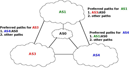
From an operational perspective, the above configuration is annoying since the network operators cannot easily predict which paths are chosen. Unfortunately, there are even more annoying BGP configurations. For example, let us consider the configuration below which is often named Bad Gadget [GW1999]
In this internetwork, there are four ASes. AS0 advertises one route towards one prefix and we only analyse the routes towards this prefix. The routing preferences of AS1, AS3 and AS4 are the following :
- AS1 prefers the path AS3:AS0 over all other paths
- AS3 prefers the path AS4:AS0 over all other paths
- AS4 prefers the path AS1:AS0 over all other paths
AS0 sends U(p,AS0) to AS1, AS3 and AS4. As this is the only route known by AS1, AS3 and AS4 towards p, they all select the direct path. Let us now consider one possible exchange of BGP messages :
- AS1 sends U(p, AS1:AS0) to AS3 and AS4. AS4 selects the path via AS1 since this is its preferred path. AS3 still uses the direct path.
- AS4 advertises U(p,AS4:AS1:AS0) to AS3.
- AS3 sends U(p, AS3:AS0) to AS1 and AS4. AS1 selects the path via AS3 since this is its preferred path. AS4 still uses the path via AS1.
- As AS1 has changed its path, it sends U(p,AS1:AS3:AS0) to AS4 and W(p) to AS3 since its new path is via AS3. AS4 switches back to the direct path.
- AS4 sends U(p,AS4:AS0) to AS1 and AS3. AS3 prefers the path via AS4.
- AS3 sends U(p,AS3:AS4:AS0) to AS1 and W(p) to AS4. AS1 switches back to the direct path and we are back at the first step.
This example shows that the convergence of BGP is unfortunately not always guaranteed as some interdomain routing policies may interfere with each other in complex ways. [GW1999] have shown that checking for global convergence is either NP-complete or NP-hard. See [GSW2002] for a more detailed discussion.
Fortunately, there are some operational guidelines [GR2001] [GGR2001] that can guarantee BGP convergence in the global Internet. To ensure that BGP will converge, these guidelines consider that there are two types of peering relationships : customer->provider and shared-cost. In this case, BGP convergence is guaranteed provided that the following conditions are fulfilled :
- The topology composed of all the directed customer->provider peering links is an acyclic graph
- An AS always prefers a route received from a customer over a route received from a shared-cost peer or a provider.
The first guideline implies that the provider of the provider of ASx cannot be a customer of ASx. Such a relationship would not make sense from an economic perspective as it would imply circular payments. Furthermore, providers are usually larger than customers.
The second guideline also corresponds to economic preferences. Since a provider earns money when sending packets to one of its customers, it makes sense to prefer such customer learned routes over routes learned from providers. [GR2001] also shows that BGP convergence is guaranteed even if an AS associates the same preference to routes learned from a shared-cost peer and routes learned from a customer.
From a theoretical perspective, these guidelines should be verified automatically to ensure that BGP will always converge in the global Internet. However, such a verification cannot be performed in practice because this would force all domains to disclose their routing policies (and few are willing to do so) and furthermore the problem is known to be NP-hard [GW1999].
In practice, researchers and operators expect that these guidelines are verified 13 in most domains. Thanks to the large amount of BGP data that has been collected by operators and researchers 14, several studies have analysed the AS-level topology of the Internet. [SARK2002] is one of the first analysis. More recent studies include [COZ2008] and [DKF+2007]
Based on these studies and [ATLAS2009], the AS-level Internet topology can be summarised as shown in the figure below.
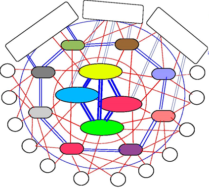
The domains on the Internet can be divided in about four categories according to their role and their position in the AS-level topology.
- the core of the Internet is composed of a dozen-twenty Tier-1 ISPs. A Tier-1 is a domain that has no provider. Such an ISP has shared-cost peering relationships with all other Tier-1 ISPs and provider->customer relationships with smaller ISPs. Examples of Tier-1 ISPs include sprint, level3 or opentransit
- the Tier-2 ISPs are national or continental ISPs that are customers of Tier-1 ISPs. These Tier-2 ISPs have smaller customers and shared-cost peering relationships with other Tier-2 ISPs. Example of Tier-2 ISPs include France Telecom, Belgacom, British Telecom, ...
- the Tier-3 networks are either stub domains such as enterprise or campus networks networks and smaller ISPs. They are customers of Tier-1 and Tier-2 ISPs and have sometimes shared-cost peering relationships
- the large content providers that are managing large datacenters. These content providers are producing a growing fraction of the packets exchanged on the global Internet [ATLAS2009]. Some of these content providers are customers of Tier-1 or Tier-2 ISPs, but they often try to establish shared-cost peering relationships, e.g. at IXPs, with many Tier-1 and Tier-2 ISPs.
Due to this organisation of the Internet and due to the BGP decision process, most AS-level paths on the Internet have a length of 3-5 AS hops.
- 3873 reads
