


In this section, we briefly describe the key features of the two main intradomain unicast routing protocols : RIP and OSPF.
RIP
The Routing Information Protocol (RIP) is the simplest routing protocol that was standardised for the TCP/IP protocol suite. RIP is defined in RFC 2453. Additional information about RIP may be found in [Malkin1999]
RIP routers periodically exchange RIP messages. The format of these messages is shown below. A RIP message is sent inside a UDP segment whose destination port is set to 521. A RIP message contains several fields. The Cmd field indicates whether the RIP message is a request or a response. Routers send one of more RIP response messages every 30 seconds. These messages contain the distance vectors that summarize the router’s routing table. The RIP request messages can be used by routers or hosts to query other routers about the content of their routing table. A typical usage is when a router boots and quickly wants to receive the RIP responses from its neighbours to compute its own routing table. The current version of RIP is version 2 defined in RFC 2453for IPv4 and RFC 2080 for IPv6.
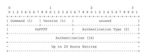
The RIP header contains an authentication field. This authentication can be used by network administrators to ensure that only the RIP messages sent by the routers that they manage are used to build the routing tables. RFC 2453 only supports a basic authentication scheme where all routers are configured with the same password and include this password in all RIP messages. This is not very secure since an attacker can know the password by capturing a single RIP message. However, this password can protect against configuration errors. Stronger authentication schemes are described in RFC 2082 and RFC 4822, but the details of these mechanisms are outside the scope of this section.
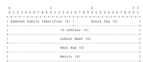
Each RIP message contains a set of route entries. Each route entry is encoded as a 20 bytes field whose format is shown below. RIP was initially designed to be suitable for different network layer protocols. Some implementations of RIP were used in XNS or IPX networks. The first field of the RIP route entry is the Address Family Identifier (AFI). This identifier indicates the type of address found in the route entry 1. IPv4 uses AFI=1. The other important fields of the route entry are the IPv4 prefix, the netmask that indicates the length of the subnet identifier and is encoded as a 32 bits netmask and the metric. Although the metric is encoded as a 32 bits field, the maximum RIP metric is 15 (for RIP, 16 = ∞)
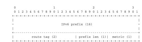
With a 20 bytes route entry, it was difficult to use the same format as above to support IPv6. Instead of defining a variable length route entry format, the designers of RFC 2080 defined a new format that does not include an AFI field. The format of the route entries used by RFC 2080 is shown below. Plen is the length of the subnet identifier in bits and the metric is encoded as one byte. The maximum metric is still 15.
The first RIP implementations sent their distance vector exactly every 30 seconds. This worked well in most networks, but some researchers noticed that routers were sometimes overloaded because they were processing too many distance vectors at the same time [FJ1994]. They collected packet traces in these networks and found that after some time the routers’ timers became synchronised, i.e. almost all routers were sending their distance vectors at almost the same time. This synchronisation of the transmission times of the distance vectors caused an overload on the routers’ CPU but also increased the convergence time of the protocol in some cases. This was mainly due to the fact that all routers set their timers to the same expiration time after having processed the received distance vectors. Sally Floyd and Van Jacobson proposed in [FJ1994] a simple solution to solve this synchronisation problem. Instead of advertising their distance vector exactly after 30 seconds, a router should send its next distance vector after a delay chosen randomly in the [15,45] interval RFC 2080. This randomisation of the delays prevents the synchronisation that occurs with a fixed delay and is now a recommended practice for protocol designers.
OSPF
Link-state routing protocols are used in IP networks. Open Shortest Path First (OSPF), defined in RFC 2328, is the link state routing protocol that has been standardised by the IETF. The last version of OSPF, which supports IPv6, is defined in RFC 5340. OSPF is frequently used in enterprise networks and in some ISP networks. However, ISP networks often use the IS-IS link-state routing protocol [ISO10589] , which was developed for the ISO CLNP protocol but was adapted to be used in IP RFC 1195 networks before the finalisation of the standardisation of OSPF. A detailed analysis of ISIS and OSPF may be found in [BMO2006] and [Perlman2000]. Additional information about OSPF may be found in [Moy1998].
Compared to the basics of link-state routing protocols that we discussed in section Link state routing, there are some particularities of OSPF that are worth discussing. First, in a large network, flooding the information about all routers and links to thousands of routers or more may be costly as each router needs to store all the information about the entire network. A better approach would be to introduce hierarchical routing. Hierarchical routing divides the network into regions. All the routers inside a region have detailed information about the topology of the region but only learn aggregated information about the topology of the other regions and their interconnections. OSPF supports a restricted variant of hierarchical routing. In OSPF’s terminology, a region is called an area.
OSPF imposes restrictions on how a network can be divided into areas. An area is a set of routers and links that are grouped together. Usually, the topology of an area is chosen so that a packet sent by one router inside the area can reach any other router in the area without leaving the area 2. An OSPF area contains two types of routers RFC 2328:
- Internal router : A router whose directly connected networks belong to the area
-
Area border routers : A router that is attached to several areas.
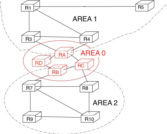
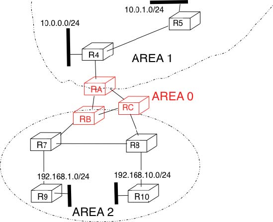
For example, the network shown in the figure below has been divided into three areas : area 1, containing routers R1, R3, R4, R5 and RA, area 2 containing R7, R8, R9, R10, RB and RC. OSPF areas are identified by a 32 bit integer, which is sometimes represented as an IP address. Among the OSPF areas, area 0, also called the backbone area has a special role. The backbone area groups all the area border routers (routers RA, RB and RC in the figure below) and the routers that are directly connected to the backbone routers but do not belong to another area (router RD in the figure below). An important restriction imposed by OSPF is that the path between two routers that belong to two different areas (e.g. R1 and R8 in the figure below) must pass through the backbone area.
Inside each non-backbone area, routers distribute the topology of the area by exchanging link state packets with the other routers in the area. The internal routers do not know the topology of other areas, but each router knows how to reach the backbone area. Inside an area, the routers only exchange link-state packets for all destinations that are reachable inside the area. In OSPF, the inter-area routing is done by exchanging distance vectors. This is illustrated by the network topology shown below.
Let us first consider OSPF routing inside area 2. All routers in the area learn a route towards 192.168.1.0/24 and 192.168.10.0/24. The two area border routers, RB and RC, create network summary advertisements. Assuming that all links have a unit link metric, these would be:
- RB advertises 192.168.1.0/24 at a distance of 2 and 192.168.10.0/24 at a distance of
- RC advertises 192.168.1.0/24 at a distance of 3 and 192.168.10.0/24 at a distance of
These summary advertisements are flooded through the backbone area attached to routers RB and RC. In its routing table, router RA selects the summary advertised by RB to reach 192.168.1.0/24 and the summary advertised by RC to reach 192.168.10.0/24. Inside area 1, router RA advertises a summary indicating that 192.168.1.0/24 and 192.168.10.0/24 are both at a distance of 3 from itself.
On the other hand, consider the prefixes 10.0.0.0/24 and 10.0.1.0/24 that are inside area 1. Router RA is the only area border router that is attached to this area. This router can create two different network summary advertisements :
- 10.0.0.0/24 at a distance of 1 and 10.0.1.0/24 at a distance of 2 from RA
- 10.0.0.0/23 at a distance of 2 from RA
The first summary advertisement provides precise information about the distance used to reach each prefix. However, all routers in the network have to maintain a route towards 10.0.0.0/24 and a route towards 10.0.1.0/24 that are both via router RA. The second advertisement would improve the scalability of OSPF by reducing the number of routes that are advertised across area boundaries. However, in practice this requires manual configuration on the border routers.
The second OSPF particularity that is worth discussing is the support of Local Area Networks (LAN). As shown in the example below, several routers may be attached to the same LAN.
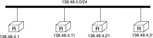
A first solution to support such a LAN with a link-state routing protocol would be to consider that a LAN is equivalent to a full-mesh of point-to-point links as if each router can directly reach any other router on the LAN. However, this approach has two important drawbacks :
- Each router must exchange HELLOs and link state packets with all the other routers on the LAN. This increases the number of OSPF packets that are sent and processed by each router.
- Remote routers, when looking at the topology distributed by OSPF, consider that there is a full-mesh of links between all the LAN routers. Such a full-mesh implies a lot of redundancy in case of failure, while in practice the entire LAN may completely fail. In case of a failure of the entire LAN, all routers need to detect the failures and flood link state packets before the LAN is completely removed from the OSPF topology by remote routers.
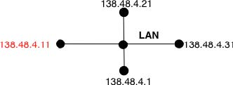
To better represent LANs and reduce the number of OSPF packets that are exchanged, OSPF handles LAN differently. When OSPF routers boot on a LAN, they elect 3 one of them as the Designated Router (DR) RFC 2328. The DR router represents the local area network, and advertises the LAN’s subnet (138.48.4.0/24 in the example above). Furthermore, LAN routers only exchange HELLO packets with the DR. Thanks to the utilisation of a DR, the topology of the LAN appears as a set of point-to-point links connected to the DR as shown in the figure below.
Network operators expect an OSPF network to be able to quickly recover from link or router failures [VPD2004]. In an OSPF network, the recovery after a failure is performed in three steps [FFEB2005] :
- the routers that are adjacent to the failure detect it quickly. The default solution is to rely on the regular exchange of HELLO packets. However, the interval between successive HELLOs is often set to 10 seconds... Setting the HELLO timer down to a few milliseconds is difficult as HELLO packets are created and processed by the main CPU of the routers and these routers cannot easily generate and process a HELLO packet every millisecond on each of their interfaces. A better solution is to use a dedicated failure detection protocol such as the Bidirectional Forwarding Detection (BFD) protocol defined in [KW2009] that can be implemented directly on the router interfaces. Another solution to be able to detect the failure is to instrument the physical and the datalink layer so that they can interrupt the router when a link fails. Unfortunately, such a solution cannot be used on all types of physical and datalink layers.
- the routers that have detected the failure flood their updated link state packets in the network
- all routers update their routing table
- 2667 reads
