


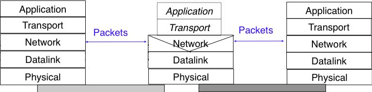
When the TCP/IP architecture and the IP protocol were defined, two type of devices were considered in the network layer : endhosts and routers. Endhosts are the sources and destinations of IP packets while routers forward packets. When a router forwards an IP packet, it consults its forwarding table, updates the packet’s TTL, recomputes its checksum and forwards it to the next hop. A router does not need to read or change the contents of the packet’s payload.
However, in today’s Internet, there exist devices that are not strictly routers but which process, sometimes modify, and forward IP packets. These devices are often called middleboxes RFC 3234. Some middleboxes only operate in the network layer, but most middleboxes are able to analyse the payload of the received packets and extract the transport header, and in some cases the application layer protocols.
In this section, we briefly describe two type of middleboxes : firewalls and network address translation (NAT) devices. A discussion of the different types of middleboxes with references may be found in RFC 3234.
Firewalls
When the Internet was only a research network interconnecting research labs, security was not a concern, and most hosts agreed to exchange packets over TCP connections with most other hosts. However, as more and more
These security problems convinced the industry that IP networks are a key part of a company’s infrastructure, that should be protected by special devices like security guards and fences are used to protect buildings. These special devices were quickly called firewalls. A typical firewall has two interfaces :
- an external interface connected to the global Internet
- an internal interface connected to a trusted network
The first firewalls included configurable packet filters. A packet filter is a set of rules defining the security policy of a network. In practice, these rules are based on the values of fields in the IP or transport layer headers. Any field of the IP or transport header can be used in a firewall rule, but the most common ones are:
- filter on the source address. For example, a company may decide to discard all packets received from one of its competitors. In this case, all packets whose source address belong to the competitor’s address block would be rejected
- filter on destination address. For example, the hosts of the research lab of a company may receive packets from the global Internet, but not the hosts of the financial department
- filter on the Protocol number found in the IP header. For example, a company may only allow its hosts to use TCP or UDP, but not other, more experimental, transport protocols
- filter on the TCP or UDP port numbers. For example, only the DNS server of a company should received UDP segments whose destination port is set to 53 or only the official SMTP servers of the company can send TCP segments whose source ports are set to 25
- filter on the TCP flags. For example, a simple solution to prohibit external hosts from opening TCP connections with hosts inside the company is to discard all TCP segments received from the external interface with only the SYN flag set.
Such firewalls are often called stateless firewalls because they do not maintain any state about the TCP connections that pass through them.
Another type of firewalls are stateful firewalls. A stateful firewall tracks the state of each TCP connection passing through it and maintains a TCB for each of these TCP connection. This TCB allows it to reassemble the received segments in order to extract their payload and perform verifications in the application layer. Some firewalls are able to inspect the URLs accessed using HTTP and log all URLs visited or block TCP connections where a dangerous URL is exchanged. Some firewalls can verify that SMTP commands are used when a TCP connection is established on port 25 or that a TCP connection on port 80 carries HTTP commands and responses.
Apart from firewalls, different types of “security” devices have been installed at the periphery of corporate networks. Intrusion Detection Systems (IDS), such as the popular snort , are stateful devices that are capable of matching reassembled segments against regular expressions corresponding to signatures of viruses, worms or other types of attacks. Deep Packet Inspection (DPI) is another type of middlebox that analyses the packet’s payload and is able to reassemble TCP segments in order to detect inappropriate usages. While IDS are mainly used in corporate networks, DPI is mainly used in Internet Service Providers. Some ISPs use DPI to detect and limit the bandwidth consumed by peer-to-peer applications. Some countries such as China or Iran use DPI to detect inappropriate Internet usage.
NAT
Network Address Translation (NAT) was proposed in [TE1993] and RFC 3022 as a short term solution to deal with the expected shortage of IPv4 addresses in the late 1980s -early 1990s. Combined with CIDR, NAT helped to significantly slow down the consumption of IPv4 addresses. A NAT is a middlebox that interconnects two networks that are using IPv4 addresses from different addressing spaces. Usually, one of these addressing spaces is the public Internet while the other is using the private IPv4 addresses defined in RFC 1918.
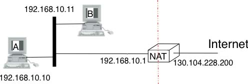
A very common deployment of NAT is in broadband access routers as shown in the figure below. The broadband access router interconnects a home network, either WiFi or Ethernet based, and the global Internet via one ISP over ADSL or CATV. A single IPv4 address is allocated to the broadband access router and network address translation allows all of the hosts attached to the home network to share a single public IPv4 address.
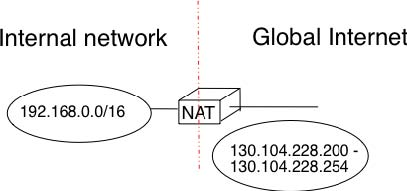
A second type of deployment is in enterprise networks as shown in the figure below. In this case, the NAT functionality is installed on a border router of the enterprise. A private IPv4 address is assigned to each enterprise host while the border router manages a pool containing several public IPv4 addresses.
As the name implies, a NAT is a device that “translates” IP addresses. A NAT maintains a mapping table between the private IP addresses used in the internal network and the public IPv4 addresses. NAT allows a large number of hosts to share a pool of IP addresses, as these hosts do not all access the global Internet at the same time.
The simplest NAT is a middlebox that uses a one-to-one mapping between a private IP address and a public IP address. To understand its operation, let us assume that a NAT, such as the one shown above, has just booted. When the NAT receives the first packet from source S in the internal network which is destined to the public Internet, it creates a mapping between internal address S and the first address of its pool of public addresses (P1). Then, it translates the received packet so that it can be sent to the public Internet. This translation is performed as followed :
- the source address of the packet (S) is replaced by the mapped public address (P1)
- the checksum of the IP header is incrementally updated as its content has changed
- if the packet carried a TCP or UDP segment, the transport layer checksum found in the included segment must also be updated as it is computed over the segment and a pseudo-header that includes the source and destination addresses
When a packet destined to P1 is received from the public Internet, the NAT consults its mapping table to find S. The received packet is translated and forwarded in the internal network.
This works as long as the pool of public IP addresses of the NAT does not become empty. In this case, a mapping must be removed from the mapping table to allow a packet from a new host to be translated. This garbage collection can be implemented by adding to each entry in the mapping table a timestamp that contains the last utilisation time of a mapping entry. This timestamp is updated each time the corresponding entry is used. Then, the garbage collection algorithm can remove the oldest mapping entry in the table.
A drawback of such a simple enterprise NAT is the size of the pool of public IPv4 addresses which is often too small to allow a large number of hosts share such a NAT. In this case, a better solution is to allow the NAT to translate both IP addresses and port numbers.
Such a NAT maintains a mapping table that maps an internal IP address and TCP port number with an external IP address and TCP port number. When such a NAT receives a packet from the internal network, it performs a lookup in the mapping table with the packet’s source IP address and source TCP port number. If a mapping is found, the source IP address and the source TCP port number of the packet are translated with the values found in the mapping table, the checksums are updated and the packet is sent to the global Internet. If no mapping is found, a new mapping is created with the first available couple (IP address, TCP port number) and the packet is translated. The entries of the mapping table are either removed at the end of the corresponding TCP connection as the NAT tracks TCP connection state like a stateful firewall or after some idle time.
When such a NAT receives a packet from the global Internet, it looks up its mapping table for the packet’s destination IP address and destination TCP port number. If a mapping is found, the packet is translated and forwarded into the internal network. Otherwise, the packet is discarded as the NAT cannot determine to which particular internal host the packet should be forwarded. For this reason,
With 216 different port numbers, a NAT may support a large number of hosts with a single public IPv4 address. However, it should be noted that some applications open a large number of TCP connections [Miyakawa2008]. Each of these TCP connections consumes one mapping entry in the NAT’s mapping table.
NAT allows many hosts to share one or a few public IPv4 addresses. However, using NAT has two important drawbacks. First, it is difficult for external hosts to open TCP connections with hosts that are behind a NAT. Some consider this to be a benefit from a security perspective. However, a NAT should not be confused with a firewall as there are some techniques to traverse NATs. Second, NAT breaks the end-to-end transparency of the network and transport layers. The main problem is when an application layer protocol uses IP addresses in some of the ADUs that it sends. A popular example is ftp defined in RFC 959. In this case, there is a mismatch between the packet header translated by the NAT and the packet payload. The only solution to solve this problem is to place an Application Level Gateway (ALG) on the NAT that understands the application layer protocol and can thus translate the IP addresses and port numbers found in the ADUs. However, defining an ALG for each application is costly and application developers should avoid using IP addresses in the messages exchanged in the application layer RFC 3235.
NAT has been very successful with IPv4. Given the size of the IPv6 addressing space, the IPv6 designers expected that NAT would never be useful with IPv6. The end-to-end transparency of IPv6 has been one of its key selling points compared to IPv4. However, the expected shortage of IPv4 addresses lead enterprise network administrators to consider IPv6 more seriously. One of the results of this analysis is that the IETF defined NAT devices [WB2008] that are IPv6 specific. Another usage of NAT with IPv6 is to allow IPv6 hosts to access IPv4 destinations and conversely. The early IPv6 specifications included the Network Address Translation -Protocol Translation (NATPT) mechanism defined in RFC 2766. This mechanism was later deprecated in RFC 4966 but has been recently restarted under the name NAT64 [BMvB2009]. A NAT64 is a middlebox that performs the IPv6<->IPv4 packet translation to allow IPv6 hosts to contact IPv4 servers RFC 6144
- 4073 reads
