


IP version 4 is the data plane protocol of the network layer in the TCP/IP protocol suite. The design of IP version 4 was based on the following assumptions :
- IP should provide an unreliable connectionless service (TCP provides reliability when required by the application)
- IP operates with the datagram transmission mode
- IP addresses have a fixed size of 32 bits
- IP must be usable above different types of datalink layers
- IP hosts exchange variable length packets
The addresses are an important part of any network layer protocol. In the late 1970s, the developers of IPv4 designed IPv4 for a research network that would interconnect some research labs and universities. For this utilisation, 32 bits wide addresses were much larger than the expected number of hosts on the network. Furthermore, 32 bits was a nice address size for software-based routers. None of the developers of IPv4 were expecting that IPv4 would become as widely used as it is today.
IPv4 addresses are encoded as a 32 bits field. IPv4 addresses are often represented in dotted-decimal format as a sequence of four integers separated by a dot. The first integer is the decimal representation of the most significant byte of the 32 bits IPv4 address, ... For example,
- 1.2.3.4 corresponds to 00000001000000100000001100000100
- 127.0.0.1 corresponds to 01111111000000000000000000000001
- 255.255.255.255 corresponds to 11111111111111111111111111111111
An IPv4 address is used to identify an interface on a router or a host. A router has thus as many IPv4 addresses as the number of interfaces that it has in the datalink layer. Most hosts have a single datalink layer interface and thus have a single IPv4 address. However, with the growth of wireless, more and more hosts have several datalink layer interfaces (e.g. an Ethernet interface and a WiFi interface). These hosts are said to be multihomed. A multihomed host with two interfaces has thus two IPv4 addresses.
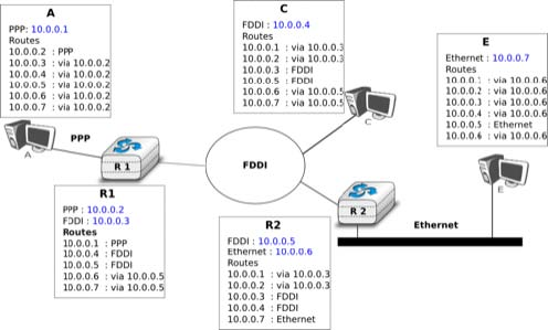
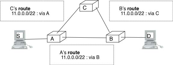
An important point to be defined in a network layer protocol is the allocation of the network layer addresses. A naive allocation scheme would be to provide an IPv4 address to each host when the host is attached to the Internet on a first come first served basis. With this solution, a host in Belgium could have address 2.3.4.5 while another host located in Africa would use address 2.3.4.6. Unfortunately, this would force all routers to maintain a specific route towards each host. The figure below shows a simple enterprise network with two routers and three hosts and the associated routing tables if such isolated addresses were used.
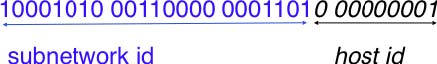
To preserve the scalability of the routing system, it is important to minimize the number of routes that are stored on each router. A router cannot store and maintain one route for each of the almost 1 billion hosts that are connected to today’s Internet. Routers should only maintain routes towards blocks of addresses and not towards individual hosts. For this, hosts are grouped in subnets based on their location in the network. A typical subnet groups all the hosts that are part of the same enterprise. An enterprise network is usually composed of several LANs interconnected by routers. A small block of addresses from the Enterprise’s block is usually assigned to each LAN. An IPv4 address is composed of two parts : a subnetwork identifier and a host identifier. The subnetwork identifier is composed of the high order bits of the address and the host identifier is encoded in the low order bits of the address. This is illustrated in the figure below.
When a router needs to forward a packet, it must know the subnet of the destination address to be able to consult its forwarding table to forward the packet. RFC 791 proposed to use the high-order bits of the address to encode the length of the subnet identifier. This led to the definition of three classes of unicast addresses 1.
|
Class |
High-order bits |
Length of subnet id |
Number of networks |
Addresses per network |
|
Class A Class B Class C |
0 10 110 |
8 bits 16 bits 24 bits |
128 16,384 2,097,152 |
16,777,216 (224) 65,536 (216) 256 (28) |
However, these three classes of addresses were not flexible enough. A class A subnet was too large for most organisations and a class C subnet was too small. Flexibility was added by the introduction of variable-length subnets in RFC 1519. With variable-length subnets, the subnet identifier can be any size, from 1 to 31 bits. Variable-length subnets allow the network operators to use a subnet that better matches the number of hosts that are placed inside the subnet. A subnet identifier or IPv4 prefix is usually 2 represented as A.B.C.D/p where A.B.C.D is the network address obtained by concatenating the subnet identifier with a host identifier containing only 0 and p is the length of the subnet identifier in bits. The table below provides examples of IP subnets.
|
Subnet |
Number of addresses |
Smallest address |
Highest address |
|
10.0.0.0/8 192.168.0.0/16 198.18.0.0/15 192.0.2.0/24 10.0.0.0/30 10.0.0.0/31 |
16,777,216 65,536 131,072 256 4 2 |
10.0.0.0 192.168.0.0 198.18.0.0 192.0.2.0 10.0.0.0 10.0.0.0 |
10.255.255.255 192.168.255.255 198.19.255.255 192.0.2.255 10.0.0.3 10.0.0.1 |
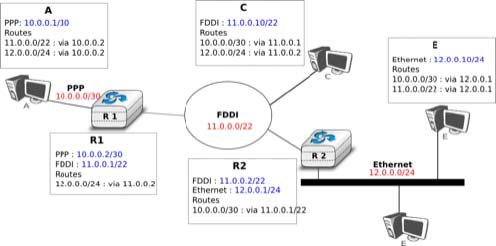
The figure below provides a simple example of the utilisation of IPv4 subnets in an enterprise network. The length of the subnet identifier assigned to a LAN usually depends on the expected number of hosts attached to the LAN. For point-to-point links, many deployments have used /30 prefixes, but recent routers are now using /31 subnets on point-to-point links RFC 3021 or do not even use IPv4 addresses on such links 3.
A second issue concerning the addresses of the network layer is the allocation scheme that is used to allocate blocks of addresses to organisations. The first allocation scheme was based on the different classes of addresses. The pool of IPv4 addresses was managed by a secretariat who allocated address blocks on a first-come first served basis. Large organisations such as IBM, BBN, as well as Stanford or the MIT were able to obtain a class A address block. Most organisations requested a class B address block containing 65536 addresses, which was suitable for most enterprises and universities. The table below provides examples of some IPv4 address blocks in the class B space.
|
Subnet |
Organisation |
|
130.100.0.0/16 |
Ericsson, Sweden |
|
130.101.0.0/16 |
University of Akron, USA |
|
130.102.0.0/16 |
The University of Queensland, Australia |
|
130.103.0.0/16 |
Lotus Development, USA |
|
130.104.0.0/16 |
Universite catholique de Louvain, Belgium |
|
130.105.0.0/16 |
Open Software Foundation, USA |
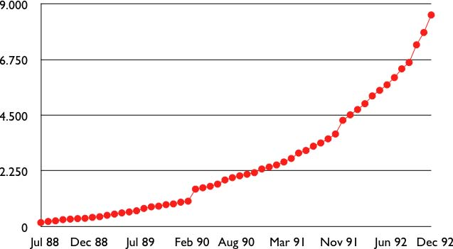
However, the Internet was a victim of its own success and in the late 1980s, many organisations were requesting blocks of IPv4 addresses and started connecting to the Internet. Most of these organisations requested class B address blocks, as class A address blocks were too large and in limited supply while class C address blocks were considered to be too small. Unfortunately, there were only 16,384 different class B address blocks and this address space was being consumed quickly. As a consequence, the routing tables maintained by the routers were growing quickly and some routers had difficulties maintaining all these routes in their limited memory 4.
Faced with these two problems, the Internet Engineering Task Force decided to develop the Classless Interdomain Routing (CIDR) architecture RFC 1518This architecture aims at allowing IP routing to scale better than the class-based architecture. CIDR contains three important modifications compared to RFC 791.
- IP address classes are deprecated. All IP equipment must use and support variable-length subnets.
- IP address blocks are no longer allocated on a first-come-first-served basis. Instead, CIDR introduces a hierarchical address allocation scheme.
- IP routers must use longest-prefix match when they lookup a destination address in their forwarding table
The last two modifications were introduced to improve the scalability of the IP routing system. The main drawback of the first-come-first-served address block allocation scheme was that neighbouring address blocks were allocated to very different organisations and conversely, very different address blocks were allocated to similar organisations. With CIDR, address blocks are allocated by Regional IP Registries (RIR) in an aggregatable manner. A RIR is responsible for a large block of addresses and a region. For example, RIPE is the RIR that is responsible for Europe. A RIR allocates smaller address blocks from its large block to Internet Service Providers RFC 2050. Internet Service Providers then allocate smaller address blocks to their customers. When an organisation requests an address block, it must prove that it already has or expects to have in the near future, a number of hosts or customers that is equivalent to the size of the requested address block.
The main advantage of this hierarchical address block allocation scheme is that it allows the routers to maintain fewer routes. For example, consider the address blocks that were allocated to some of the Belgian universities as shown in the table below.
|
Address block |
Organisation |
|
130.104.0.0/16 134.58.0.0/16 138.48.0.0/16 139.165.0.0/16 164.15.0.0/16 |
Universite catholique de Louvain Katholiek Universiteit Leuven Facultes universitaires Notre-Dame de la Paix Universite de Liege Universite Libre de Bruxelles |
These universities are all connected to the Internet exclusively via Belnet. As each university has been allocated a different address block, the routers of Belnet must announce one route for each university and all routers on the Internet must maintain a route towards each university. In contrast, consider all the high schools and the government institutions that are connected to the Internet via Belnet. An address block was assigned to these institutions after the introduction of CIDR in the 193.190.0.0/15 address block owned by Belnet. With CIDR, can announce a single route towards 193.190.0.0/15 that covers all of these high schools.
However, there is one difficulty with the aggregatable variable length subnets used by CIDR. Consider for example FEDICT, a government institution that uses the 193.191.244.0/23 address block. Assume that in addition to being connected to the Internet via Belnet , FEDICT also wants to be connected to another Internet Service Provider. The FEDICT network is then said to be multihomed. This is shown in the figure below.
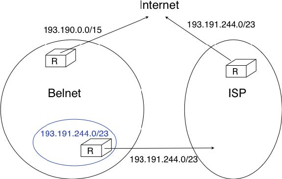
With such a multihomed network, routers R1 and R2 would have two routes towards IPv4 address 193.191.245.88 : one route via Belnet (193.190.0.0/15) and one direct route (193.191.244.0/23). Both routes match IPv4 address 193.192.145.88. Since RFC 1519 when a router knows several routes towards the same destination address, it must forward packets along the route having the longest prefix length. In the case of 193.191.245.88, this is the route 193.191.244.0/23 that is used to forward the packet. This forwarding rule is called the longest prefix match or the more specific match. All IPv4 routers implement this forwarding rule.
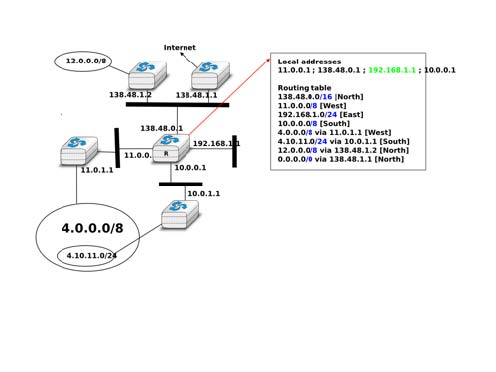
To understand the longest prefix match forwarding, consider the figure below. With this rule, the route 0.0.0.0/0 plays a particular role. As this route has a prefix length of 0 bits, it matches all destination addresses. This route is often called the default route.
- a packet with destination 192.168.1.1 received by router R is destined to the router itself. It is delivered to the appropriate transport protocol.
- a packet with destination 11.2.3.4 matches two routes : 11.0.0.0/8 and 0.0.0.0/0. The packet is forwarded on the West interface.
- a packet with destination 130.4.3.4 matches one route : 0.0.0.0/0. The packet is forwarded on the North interface.
- a packet with destination 4.4.5.6 matches two routes : 4.0.0.0/8 and 0.0.0.0/0. The packet is forwarded on the West interface.
- a packet with destination 4.10.11.254 matches three routes : 4.0.0.0/8, 4.10.11.0/24 and ‘0.0.0.0/0. The packet is forwarded on the South interface.
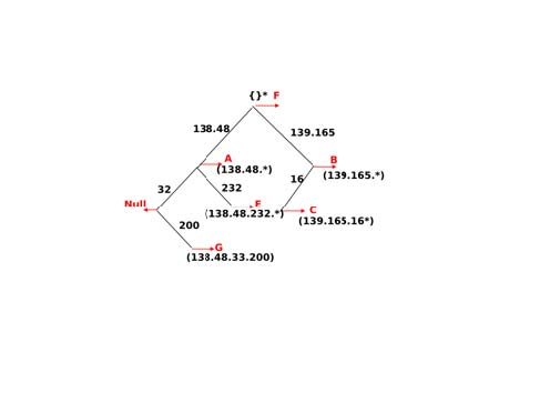
The longest prefix match can be implemented by using different data structures. One possibility is to use a trie. The figure below shows a trie that encodes six routes having different outgoing interfaces.
Most unicast IPv4 addresses can appear as source and destination addresses in packets on the global Internet. However, it is worth noting that some blocks of IPv4 addresses have a special usage, as described in RFC 5735. These include :
- 0.0.0.0/8, which is reserved for self-identification. A common address in this block is 0.0.0.0, which is sometimes used when a host boots and does not yet know its IPv4 address.
- 127.0.0.0/8, which is reserved for loopback addresses. Each host implementing IPv4 must have a loopback interface (that is not attached to a datalink layer). By convention, IPv4 address 127.0.0.1 is assigned to this interface. This allows processes running on a host to use TCP/IP to contact other processes running on the same host. This can be very useful for testing purposes.
- 10.0.0.0/8, 172.16.0.0/12 and 192.168.0.0/16 are reserved for private networks that are not directly attached to the Internet. These addresses are often called private addresses or RFC 1918 addresses.
- 169.254.0.0/16 is used for link-local addresses RFC 3927. Some hosts use an address in this block when they are connected to a network that does not allocate addresses as expected.
IPv4 packets
Now that we have clarified the allocation of IPv4 addresses and the utilisation of the longest prefix match to forward IPv4 packets, we can have a more detailed look at IPv4 by starting with the format of the IPv4 packets. The IPv4 packet format was defined in RFC 791. Apart from a few clarifications and some backward compatible changes, the IPv4 packet format did not change significantly since the publication of RFC 791. All IPv4 packets use the 20 bytes header shown below. Some IPv4 packets contain an optional header extension that is described later.
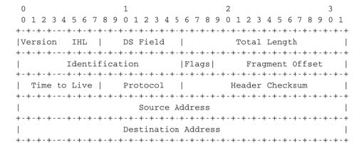
The main fields of the IPv4 header are :
- a 4 bits version that indicates the version of IP used to build the header. Using a version field in the header allows the network layer protocol to evolve.
- a 4 bits IP Header Length (IHL) that indicates the length of the IP header in 32 bits words. This field allows IPv4 to use options if required, but as it is encoded as a 4 bits field, the IPv4 header cannot be longer than 64 bytes.
- an 8 bits DS field that is used for Quality of Service and whose usage is described later.
- an 8 bits Protocol field that indicates the transport layer protocol that must process the packet’s payload at the destination. Common values for this field are 5 for TCP and 17 for UDP
- a 16 bits length field that indicates the total length of the entire IPv4 packet (header and payload) in bytes. This implies that an IPv4 packet cannot be longer than 65535 bytes.
- a 32 bits source address field that contains the IPv4 address of the source host
- a 32 bits destination address field that contains the IPv4 address of the destination host
- a 16 bits checksum that protects only the IPv4 header against transmission errors
The other fields of the IPv4 header are used for specific purposes. The first is the 8 bits Time To Live (TTL) field. This field is used by IPv4 to avoid the risk of having an IPv4 packet caught in an infinite loop due to a transient or permanent error in routing tables 6. Consider for example the situation depicted in the figure below where destination D uses address 11.0.0.56. If S sends a packet towards this destination, the packet is forwarded to router B which forwards it to router C that forwards it back to router A, etc.
Unfortunately, such loops can occur for two reasons in IP networks. First, if the network uses static routing, the loop can be caused by a simple configuration error. Second, if the network uses dynamic routing, such a loop can occur transiently, for example during the convergence of the routing protocol after a link or router failure. The TTL field of the IPv4 header ensures that even if there are forwarding loops in the network, packets will not loop forever. Hosts send their IPv4 packets with a positive TTL (usually 64 or more 7). When a router receives an IPv4 packet, it first decrements the TTL by one. If the TTL becomes 0, the packet is discarded and a message is sent back to the packet’s source (see section ICMP). Otherwise, the router performs a lookup in its forwarding table to forward the packet.
A second problem for IPv4 is the heterogeneity of the datalink layer. IPv4 is used above many very different datalink layers. Each datalink layer has its own characteristics and as indicated earlier, each datalink layer is characterised by a maximum frame size. From IP’s point of view, a datalink layer interface is characterised by its Maximum Transmission Unit (MTU). The MTU of an interface is the largest IPv4 packet (including header) that it can send. The table below provides some common MTU sizes 8.
|
Datalink layer |
MTU |
|
Ethernet |
1500 bytes |
|
WiFi |
2272 bytes |
|
ATM (AAL5) |
9180 bytes |
|
802.15.4 |
102 or 81 bytes |
|
Token Ring |
4464 bytes |
|
FDDI |
4352 bytes |
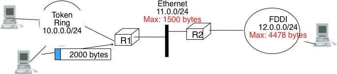
Although IPv4 can send 64 KBytes long packets, few datalink layer technologies that are used today are able to send a 64 KBytes IPv4 packet inside a frame. Furthermore, as illustrated in the figure below, another problem is that a host may send a packet that would be too large for one of the datalink layers used by the intermediate routers.
To solve these problems, IPv4 includes a packet fragmentation and reassembly mechanism. Both hosts and intermediate routers may fragment an IPv4 packet if the packet is too long to be sent via the datalink layer. In IPv4, fragmentation is completely performed in the IP layer and a large IPv4 is fragmented into two or more IPv4 packets (called fragments). The IPv4 fragments of a large packet are normal IPv4 packets that are forwarded towards the destination of the large packet by intermediate routers.
The IPv4 fragmentation mechanism relies on four fields of the IPv4 header : Length, Identification, the flags and the Fragment Offset. The IPv4 header contains two flags : More fragments and Don’t Fragment (DF). When the DF flag is set, this indicates that the packet cannot be fragmented.
The basic operation of the IPv4 fragmentation is as follows. A large packet is fragmented into two or more fragments. The size of all fragments, except the last one, is equal to the Maximum Transmission Unit of the link used to forward the packet. Each IPv4 packet contains a 16 bits Identification field. When a packet is fragmented, the Identification of the large packet is copied in all fragments to allow the destination to reassemble the received fragments together. In each fragment, the Fragment Offset indicates, in units of 8 bytes, the position of the payload of the fragment in the payload of the original packet. The Length field in each fragment indicates the length of the payload of the fragment as in a normal IPv4 packet. Finally, the More fragments flag is set only in the last fragment of a large packet.
The following pseudo-code details the IPv4 fragmentation, assuming that the packet does not contain options.
#mtu : maximum size of the packet (including header) of outgoing link
if p.len < mtu :     send(p)
# packet is too large
maxpayload=8*int((mtu-20)/8) # must be n times 8 bytes
if p.flags==’DF’ :     discard(p)
# packet must be fragmented
payload=p[IP].payload
pos=0
while len(payload) > 0 :     if len(payload) > maxpayload :       toSend=IP(dest=p.dest,src=p.src,             ttl=p.ttl, id=p.id,             frag=p.frag+(pos/8),             len=mtu, proto=p.proto)/payload[0:maxpayload]       pos=pos+maxpayload       payload=payload[maxpayload+1:]     else       toSend=IP(dest=p.dest,src=p.src,              ttl=p.ttl, id=p.id,              frag=p.frag+(pos/8),              flags=p.flags,              len=len(payload), proto=p.proto)/payload     forward(toSend)
The fragments of an IPv4 packet may arrive at the destination in any order, as each fragment is forwarded independently in the network and may follow different paths. Furthermore, some fragments may be lost and never reach the destination.
The reassembly algorithm used by the destination host is roughly as follows. First, the destination can verify whether a received IPv4 packet is a fragment or not by checking the value of the More fragments flag and the Fragment Offset. If the Fragment Offset is set to 0 and the More fragments flag is reset, the received packet has not been fragmented. Otherwise, the packet has been fragmented and must be reassembled. The reassembly algorithm relies on the Identification field of the received fragments to associate a fragment with the corresponding packet being reassembled. Furthermore, the Fragment Offset field indicates the position of the fragment payload in the original unfragmented packet. Finally, the packet with the More fragments flag reset allows the destination to determine the total length of the original unfragmented packet.
Note that the reassembly algorithm must deal with the unreliability of the IP network. This implies that a fragment may be duplicated or a fragment may never reach the destination. The destination can easily detect fragment duplication thanks to the Fragment Offset. To deal with fragment losses, the reassembly algorithm must bound the time during which the fragments of a packet are stored in its buffer while the packet is being reassembled. This can be implemented by starting a timer when the first fragment of a packet is received. If the packet has not been reassembled upon expiration of the timer, all fragments are discarded and the packet is considered to be lost.
The original IP specification, in RFC 791, defined several types of options that can be added to the IP header. Each option is encoded using a type length value format. They are not widely used today and are thus only briefly described. Additional details may be found in RFC 791.
The most interesting options in IPv4 are the three options that are related to routing. The Record route option was defined to allow network managers to determine the path followed by a packet. When the Record route option was present, routers on the packet’s path had to insert their IP address in the option. This option was implemented, but as the optional part of the IPv4 header can only contain 44 bytes, it is impossible to discover an entire path on the global Internet. traceroute(8), despite its limitations, is a better solution to record the path towards a destination.
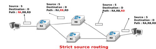
The other routing options are the Strict source route and the Loose source route option. The main idea behind these options is that a host may want, for any reason, to specify the path to be followed by the packets that it sends. The Strict source route option allows a host to indicate inside each packet the exact path to be followed. The Strict source route option contains a list of IPv4 address and a pointer to indicate the next address in the list. When a router receives a packet containing this option, it does not lookup the destination address in its routing table but forwards the packet directly to the next router in the list and advances the pointer. This is illustrated in the figure below where S forces its packets to follow the RA-RB-RD path.
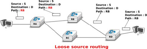
The maximum length of the optional part of the IPv4 header is a severe limitation for the Strict source route option as for the Record Route option. The Loose source route option does not suffer from this limitation. This option allows the sending host to indicate inside its packet some of the routers that must be traversed to reach the destination. This is shown in the figure below. S sends a packet containing a list of addresses and a pointer to the next router in the list. Initially, this pointer points to RB. When RA receives the packet sent by S, it looks up in its forwarding table the address pointed in the Loose source route option and not the destination address. The packet is then forwarded to router RB that recognises its address in the option and advances the pointer. As there is no address listed in the Loose source route option anymore, RB and other downstream routers forward the packet by performing a lookup for the destination address.
- 2527 reads
