


This is the framing problem. It can be defined as : “How does a sender encode frames so that the receiver can efficiently extract them from the stream of bits that it receives from the physical layer”.
A first solution to solve the framing problem is to require the physical layer to remain idle for some time after the transmission of each frame. These idle periods can be detected by the receiver and serve as a marker to delineate frame boundaries. Unfortunately, this solution is not sufficient for two reasons. First, some physical layers cannot remain idle and always need to transmit bits. Second, inserting an idle period between frames decreases the maximum bandwidth that can be achieved by the datalink layer.
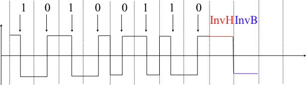
Some physical layers provide an alternative to this idle period. All physical layers are able to send and receive physical symbols that represent values 0 and 1. However, for various reasons that are outside the scope of this chapter, several physical layers are able to exchange other physical symbols as well. For example, the Manchester encoding used in several physical layers can send four different symbols. The Manchester encoding is a differential encoding scheme in which time is divided into fixed-length periods. Each period is divided in two halves and two different voltage levels can be applied. To send a symbol, the sender must set one of these two voltage levels during each half period. To send a 1 (resp. 0), the sender must set a high (resp. low) voltage during the first half of the period and a low (resp. high) voltage during the second half. This encoding ensures that there will be a transition at the middle of each period and allows the receiver to synchronise its clock to the sender’s clock. Apart from the encodings for 0 and 1, the Manchester encoding also supports two additional symbols : InvH and InvB where the same voltage level is used for the two half periods. By definition, these two symbols cannot appear inside a frame which is only composed of 0 and 1. Some technologies use these special symbols as markers for the beginning or end of frames.
Unfortunately, multi-symbol encodings cannot be used by all physical layers and a generic solution which can be used with any physical layer that is able to transmit and receive only 0 and 1 is
required. This generic solution is called stuffing and two variants exist : bit stuffing and character stuffing. To enable a receiver to easily delineate the frame boundaries, these two
techniques reserve special bit strings as frame boundary markers and encode the frames so that these special bit strings do not appear inside the frames.
Bit stuffing reserves the 01111110 bit string as the frame boundary marker and ensures that there will never be six consecutive 1 symbols transmitted by the physical layer
inside a frame. With bit stuffing, a frame is sent as follows. First, the sender transmits the marker, i.e. 01111110. Then, it sends all the bits of the frame and inserts an additional
bit set to 0 after each sequence of five consecutive 1 bits. This ensures that the sent frame never contains a sequence of six consecutive bits set to 1. As a consequence, the marker pattern
cannot appear inside the frame sent. The marker is also sent to mark the end of the frame. The receiver performs the opposite to decode a received frame. It first detects the beginning of the
frame thanks to the 01111110 marker. Then, it processes the received bits and counts the number of consecutive bits set to 1. Ifa 0 follows five consecutive bits set to 1, this bit is removed
since it was inserted by the sender. If a 1 follows five consecutive bits sets to 1, it indicates a marker if it is followed by a bit set to 0. The table below illustrates the application of
bit stuffing to some frames.
|
Original frame |
Transmitted frame |
|
0001001001001001001000011 0110111111111111111110010 01111110 |
01111110000100100100100100100001101111110 01111110011011111011111011111011001001111110 0111111001111101001111110 |
For example, consider the transmission of 0110111111111111111110010. The sender will first send the 01111110 marker followed by 011011111. After these five consecutive bits set to 1, it inserts a bit set to 0 followed by 11111. A new 0 is inserted, followed by 11111. A new 0 is inserted followed by the end of the frame 110010 and the 01111110 marker.
Bit stuffing increases the number of bits required to transmit each frame. The worst case for bit stuffing is of course a long sequence of bits set to 1 inside the frame. If transmission errors occur, stuffed bits or markers can be in error. In these cases, the frame affected by the error and possibly the next frame will not be correctly decoded by the receiver, but it will be able to resynchronise itself at the next valid marker.
Bit stuffing can be easily implemented in hardware. However, implementing it in software is difficult given the higher overhead of bit manipulations in software. Software implementations prefer to process characters than bits, software-based datalink layers usually use character stuffing. This technique operates on frames that contain an integer number of 8-bit characters. Some characters are used as markers to delineate the frame boundaries. Many character stuffing techniques use the DLE, STX and ETX characters of the ASCII character set. DLE STX (resp. DLE ETX) is used to mark the beginning (end) of a frame. When transmitting a frame, the sender adds a DLE character after each transmitted DLE character. This ensures that none of the markers can appear inside the transmitted frame. The receiver detects the frame boundaries and removes the second DLE when it receives two consecutive DLE characters. For example, to transmit frame 1 2 3 DLE STX 4, a sender will first send DLE STX as a marker, followed by 1 2 3 DLE. Then, the sender transmits an additional DLE character followed by STX 4 and the DLE ETX marker.
|
Original frame |
Transmitted frame |
|
1 2 3 4 1 2 3 DLE STX 4 DLE STX DLE ETX |
DLE STX 1 2 3 4 DLE ETX DLE STX 1 2 3 DLE DLE STX 4 DLE ETX DLE STX DLE DLE STX DLE DLE ETX DLE ETX |
Character stuffing , like bit stuffing, increases the length of the transmitted frames. For character stuffing, the worst frame is a frame containing many DLE characters. When transmission errors occur, the receiver may incorrectly decode one or two frames (e.g. if the errors occur in the markers). However, it will be able to resynchronise itself with the next correctly received markers.
- 2113 reads
