Problem 5.1: Sampling and Filtering
The signal s (t) is bandlimited to 4 kHz. We want to sample it, but it has been subjected to various signal processing manipulations.
- What sampling frequency (if any works) can be used to sample the result of passing s (t) through an RC highpass filter with R = 10kΩ and C = 8nF ?
- What sampling frequency (if any works) can be used to sample the derivative of s (t)?
- The signal s (t) has been modulated by an 8 kHz sinusoid having an unknown phase: the resulting signal is s (t) sin (2πf0t + ϕ) , with f0 = 8kHz and ϕ =? Can the modulated signal be sampled so that the original signal can be recovered from the modulated signal regardless of the phase value φ? If so, show how and find the smallest sampling rate that can be used; if not, show why not.
Problem 5.2: Non-Standard Sampling
Using the properties of the Fourier series can ease finding a signal's spectrum.
- Suppose a signal s (t) is periodic with period T . If ck represents the signal's Fourier series
coefficients, what are the Fourier series coefficients of

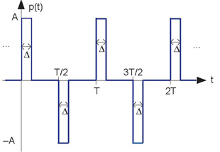
- Find the Fourier series of the signal p (t) shown in Figure 5.25 (Pulse Signal).
- Suppose this signal is used to sample a signal bandlimited to
 Find an expression for and sketch the spectrum of the sampled signal.
- Does aliasing occur? If so, can a change in sampling rate prevent aliasing; if not, show how the signal can be recovered from these samples.
Problem 5.3: A Different Sampling Scheme
A signal processing engineer from Texas A&M claims to have developed an improved sampling scheme. He multiplies the bandlimited signal by the depicted periodic pulse signal to perform sampling (Figure 5.26).
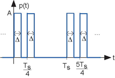
- Find the Fourier spectrum of this signal.
- Will this scheme work? If so, how should TS be related to the signal's bandwidth? If not, why not?
Problem 5.4: Bandpass Sampling
The signal s(t) has the indicated spectrum.

- What is the minimum sampling rate for this signal suggested by the Sampling Theorem?
- Because of the particular structure of this spectrum, one wonders whether a lower sampling rate could be used. Show that this is indeed the case, and find the system that reconstructs s (t) from its samples.
Problem 5.5: Sampling Signals
If a signal is bandlimited to W Hz, we can sample it at any rate  and recover the waveform exactly. This statement of the Sampling Theorem can be taken to mean that all information about the
original signal can be extracted from the samples. While true in principle, you do have to be careful how you do so. In addition to the rms value of a signal, an important aspect of a signal is
its peak value, which equals max {|s (t) |} .
| 1. | Let s (t) be a sinusoid having frequency W Hz. If we sample it at precisely the Nyquist rate, how accurately do the samples convey the sinusoid's amplitude? In other words, find the worst case example. |
| 2. | How fast would you need to sample for the amplitude estimate to be within 5% of the true value? |
| 3. |
Another issue in sampling is the inherent amplitude quantization produced by A/D converters. Assume the maximum voltage allowed by the converter is Vmax volts and that
it quantizes amplitudes to b bits. We can express the quantized sample  as as  where where  represents the quantization error at the nth sample. Assuming the converter rounds, how large is maximum
quantization error? represents the quantization error at the nth sample. Assuming the converter rounds, how large is maximum
quantization error?
|
| 4. | We can describe the quantization error as noise, with a power proportional to the square of the maximum error. What is the signal-to-noise ratio of the quantization error for a full-range sinusoid? Express your result in decibels. |
Problem 5.6: Hardware Error
An A/D converter has a curious hardware problem: Every other sampling pulse is half its normal amplitude (Figure 5.28).
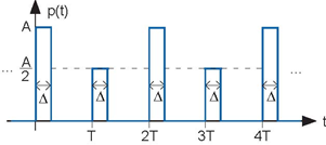
- Find the Fourier series for this signal.
- Can this signal be used to sample a bandlimited signal having highest frequency

Problem 5.7: Simple D/A Converter
Commercial digital-to-analog converters don't work this way, but a simple circuit illustrates how they work. Let's assume we have a B-bit converter. Thus, we want to convert numbers having a B-bit representation into a voltage proportional to that number. The first step taken by our simple converter is to represent the number by a sequence of B pulses occurring at multiples of a time interval T . The presence of a pulse indicates a "1" in the corresponding bit position, and pulse absence means a "0" occurred. For a 4-bit converter, the number 13 has the binary representation 1101 (1310 =1 × 23 +1 × 22 +0 × 21 +1 × 20 ) and would be represented by the depicted pulse sequence. Note that the pulse sequence is "backwards" from the binary representation. We'll see why that is.
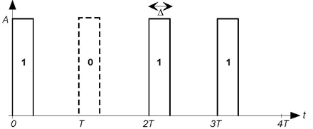
This signal (Figure 5.29) serves as the input to a first-order RC lowpass filter. We want to design the filter and the parameters Δ and T so that the output voltage at time 4T (for a 4-bit converter) is proportional to the number. This combination of pulse creation and filtering constitutes our simple D/A converter. The requirements are
- The voltage at time t=4T should diminish by a factor of 2 the further the pulse occurs from this time. In other words, the voltage due to a pulse at 3T should be twice that of a pulse produced at 2T , which in turn is twice that of a pulse at T , etc.
- The 4-bit D/A converter must support a 10 kHz sampling rate.
Show the circuit that works. How do the converter's parameters change with sampling rate and number of bits in the converter?
Problem 5.8: Discrete-Time Fourier Transforms Find the Fourier transforms of the following sequences, where s (n) is some sequence having Fourier
transform 
a. 
b. 
c. 
d. 
Problem 5.9: Spectra of Finite-Duration Signals
Find the indicated spectra for the following signals.
- The discrete-time Fourier transform of

- The discrete-time Fourier transform of

- The discrete-time Fourier transform of

- The length-8 DFT of the previous signal.
Problem 5.10: Just Whistlin’
Sammy loves to whistle and decides to record and analyze his whistling in lab. He is a very good whistler; his whistle is a pure sinusoid that can be described by sa (t) = sin (4000t) . To analyze the spectrum, he samples his recorded whistle with a sampling interval of TS =2.5 × 10⁻⁴ to obtain s (n)= sa (nTS) . Sammy (wisely) decides to analyze a few samples at a time, so he grabs 30 consecutive, but arbitrarily chosen, samples. He calls this sequence x (n) and realizes he can write it as
x (n) = sin (4000nTS + θ) , n = {0,..., 29}
- Did Sammy under-or over-sample his whistle?
- What is the discrete-time Fourier transform of x (n) and how does it depend on θ?
- How does the 32-point DFT of x (n) depend on θ?
Problem 5.11: Discrete-Time Filtering
We can find the input-output relation for a discrete-time filter much more easily than for analog filters. The key idea is that a sequence can be written as a weighted linear combination of unit samples.
- Show that
 w here δ
(n) is the unit-sample.

- If h (n) denotes the unit-sample response the output of a discrete-time linear, shift-invariant filter to a unit-sample input find an expression for the output.
- In particular, assume our filter is FIR, with the unit-sample response having duration q +1. If the input has duration N, what is the duration of the filter's output to this signal?
- Let the filter be a boxcar averager:
 for
n={0,...,q} and zero otherwise. Let the input be a pulse of unit height and duration N. Find the filter's output when
  q an odd integer.
Problem 5.12: A Digital Filter
A digital filter has the depicted (Figure 5.30) unit-sample response.
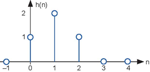
- What is the difference equation that defines this filter's input-output relationship?
- What is this filter's transfer function?
- What is the filter's output when the input is

Problem 5.13: A Special Discrete-Time Filter
Consider a FIR filter governed by the difference equation

- Find this filter's unit-sample response.
- Find this filter's transfer function. Characterize this transfer function (i.e., what classic filter category does it fall into).
- Suppose we take a sequence and stretch it out by a factor of three.

Sketch the sequence x (n) for some example s (n). What is the filter's output to this input? In particular, what is the output at the indices where the input x (n) is intentionally zero? Now how would you characterize this system?
Problem 5.14: Simulating the Real World
Much of physics is governed by differential equations, and we want to use signal processing methods to simulate physical problems. The idea is to replace the derivative with a discrete-time approximation and solve the resulting differential equation. For example, suppose we have the differential equation

and we approximate the derivative by

where T essentially mounts to a sampling interval.
- What is the diference equation that must be solved to approximate the differential equation?
- When x (t)= u (t) , the unit step, what will be the simulated output?
- Assuming x (t) is a sinusoid, how should the sampling interval T be chosen so that the approximation works well?
Problem 5.15: Derivatives
The derivative of a sequence makes little sense, but still, we can approximate it. The digital filter described by the difference equation
y (n)= x (n) − x (n − 1)
resembles the derivative formula. We want to explore how well it works.
- What is this filter's transfer function?
- What is the filter's output to the depicted triangle input (Figure 5.31)?
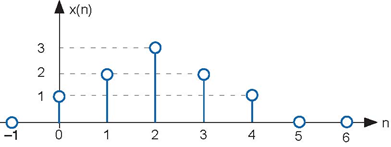
- Suppose the signal x (n) is a sampled analog signal: x (n) = x(nTs). Under what conditions will the filter act like a
differentiator? In other words, when will y (n) be proportional
to

Problem 5.16: The DFT
Let's explore the DFT and its properties.
- What is the length-K DFT of length-N boxcar sequence, where N < K?
- Consider the special case where K = 4. Find the inverse DFT of the product of the DFTs of two length-3 boxcars.
- If we could use DFTs to perform linear filtering, it should be true that the product of the input's DFT and the unit-sample response's DFT equals the output's DFT. So that you can use what you just calculated, let the input be a boxcar signal and the unit-sample response also be a boxcar. The result of part (b) would then be the filter's output if we could implement the filter with length-4 DFTs. Does the actual output of the boxcar-filter equal the result found in the previous part?
- What would you need to change so that the product of the DFTs of the input and unit-sample response in this case equaled the DFT of the filtered output?
Problem 5.17: DSP Tricks
Sammy is faced with computing lots of discrete Fourier transforms. He will, of course, use the FFT algorithm, but he is behind schedule and needs to get his results as quickly as possible. He gets the idea of computing two transforms at one time by computing the transform of s (n)= s1 (n)+ js2 (n) , where s1 (n) and s2 (n) are two real-valued signals of which he needs to compute the spectra. The issue is whether he can retrieve the individual DFTs from the result or not.
- What will be the DFT S (k) of this complex-valued signal in terms of S1 (k) and S2 (k), the DFTs of the original signals?
- Sammy's friend, an Aggie who knows some signal processing, says that retrieving the wanted DFTs is easy: "Just find the real and imaginary parts of S (k)." Show that this approach is too simplistic.
- While his friend's idea is not correct, it does give him an idea. What approach will work? Hint: Use the symmetry properties of the DFT.
- How does the number of computations change with this approach? Will Sammy's idea ultimately lead to a faster computation of the required DFTs?
Problem 5.18: Discrete Cosine Transform (DCT)
The discrete cosine transform of a length-N sequence is defined to be

Note that the number of frequency terms is 2N − 1: k = {0,..., 2N − 1}.
- Find the inverse DCT.
- Does a Parseval's Theorem hold for the DCT?
- You choose to transmit information about the signal s (n) according to the DCT coefficients. You could only send one, which one would you send?
Problem 5.19: A Digital Filter
A digital filter is described by the following difference equation:

- What is this filter's unit sample response?
- What is this filter's transfer function?
- What is this filter's output when the input is

Problem 5.20: Another Digital Filter
A digital filter is determined by the following difference equation.
y (n)= y (n − 1) + x (n) − x (n − 4)
b) What is the filter's transfer function? How would you characterize this filter (lowpass, highpass, special purpose, ...)?
c) Find the filter's output when the input is the sinusoid

d) In another case, the input sequence is zero for n < 0, then becomes nonzero. Sammy measures the output to be y (n)= δ (n)+ δ (n − 1) . Can his measurement be correct? In other words, is there an input that can yield this output? If so, find the input x (n) that gives rise to this output. If not, why not?
Problem 5.21: Yet Another Digital Filter
A filter has an input-output relationship given by the difference equation

- What is the filter's transfer function? How would you characterize it?
- What is the filter's output when the input equals

- What is the filter's output when the input is the depicted discrete-time square wave (Figure 5.32)?
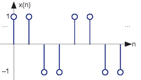
Problem 5.22: A Digital Filter in the Frequency Domain
We have a filter with the transfer function

operating on the input signal x (n)= δ (n) − δ (n − 2) that yields the output y (n).
a) What is the filter's unit-sample response?
b) What is the discrete-Fourier transform of the output?
c) What is the time-domain expression for the output?
Problem 5.23: Digital Filters
A discrete-time system is governed by the difference equation

- Find the transfer function for this system.
- What is this system's output when the input is

- If the output is observed to be y (n)= δ (n)+ δ (n − 1), then what is the input?
Problem 5.24: Digital Filtering
A digital filter has an input-output relationship expressed by the diference equation

- Plot the magnitude and phase of this filter's transfer function.
- What is this filter's output when

Problem 5.25: Detective Work
The signal x (n) equals δ (n) − δ (n − 1).
- Find the length-8 DFT (discrete Fourier transform) of this signal.
- You are told that when x (n) served as the input to a linear FIR (finite impulse response) filter, the output was y (n)= δ (n) −δ (n − 1) + 2δ (n − 2) . Is this statement true? If so, indicate why and find the system's unit sample response; if not, show why not.
Problem 5.26:
A discrete-time, shift invariant, linear system produces an output y (n)= {1, −1, 0, 0,... } when its input x (n) equals a unit sample.
- Find the difference equation governing the system.
- Find the output when x (n) = cos (2πf0n).
- How would you describe this system's function?
Problem 5.27: Time Reversal has Uses
A discrete-time system has transfer function H(ej2πf) . A signal x (n) is passed through this system to yield the signal w (n). The time-reversed signal w (−n) is then passed through the system to yield the time-reversed output y (-n). What is the transfer function between x (n) and y (n)?
Problem 5.28: Removing "Hum"
The slang word "hum" represents power line waveforms that creep into signals because of poor circuit construction. Usually, the 60 Hz signal (and its harmonics) are added to the desired signal. What we seek are filters that can remove hum. In this problem, the signal and the accompanying hum have been sampled; we want to design a digital filter for hum removal.
- Find filter coefficients for the length-3 FIR filter that can remove a sinusoid having digital frequency f0 from its input.
- Assuming the sampling rate is fs to what analog frequency does f0 correspond?
- A more general approach is to design a filter having a frequency response magnitude proportional to
- the absolute value of a cosine: |H(ej2πf) |∝|cos (πfN) | . In this way, not only can the fundamental but also its first few harmonics be removed. Select the parameter N and the sampling rate so that the frequencies at which the cosine equals zero correspond to 60 Hz and its odd harmonics through the fifth.
- Find the difference equation that defines this filter.
Problem 5.29: Digital AM Receiver
Thinking that digital implementations are always better, our clever engineer wants to design a digital AM receiver. The receiver would bandpass the received signal, pass the result through an A/D converter, perform all the demodulation with digital signal processing systems, and end with a D/A converter to produce the analog message signal. Assume in this problem that the carrier frequency is always a large even multiple of the message signal's bandwidth W.
- What is the smallest sampling rate that would be needed?
- Show the block diagram of the least complex digital AM receiver.
- Assuming the channel adds white noise and that a b-bit A/D converter is used, what is the output's signal-to-noise ratio?
Problem 5.30: DFTs
A problem on Samantha's homework asks for the 8-point DFT of the discrete-time signal δ (n − 1) + δ (n − 7).
- What answer should Samantha obtain?
- As a check, her group partner Sammy says that he computed the inverse DFT of her answer and got δ (n + 1) + δ (n − 1). Does Sammy's result mean that Samantha's answer is wrong?
- The homework problem says to lowpass-filter the sequence by multiplying its DFT by

and then computing the inverse DFT. Will this filtering algorithm work? If so, find the filtered output; if not, why not?
Problem 5.31: Stock Market Data Processing
Because a trading week lasts five days, stock markets frequently compute running averages each day over the previous five trading days to smooth price fluctuations. The technical stock analyst at the Buy-Lo Sell-Hi brokerage firm has heard that FFT filtering techniques work better than any others (in terms of producing more accurate averages).
- What is the diference equation governing the fve-day averager for daily stock prices?
- Design an efcient FFT-based filtering algorithm for the broker. How much data should be processed at once to produce an efcient algorithm? What length transform should be used?
- Is the analyst's information correct that FFT techniques produce more accurate averages than any others? Why or why not?
Problem 5.32: Echoes
Echoes not only occur in canyons, but also in auditoriums and telephone circuits. In one situation where the echoed signal has been sampled, the input signal x (n) emerges as x (n)+ a1x (n − n1)+ a2x (n − n2).
- Find the difference equation of the system that models the production of echoes.
- To simulate this echo system, ELEC 241 students are asked to write the most efficient (quickest) program that has the same input-output relationship. Suppose the duration of
x(n) is 1,000 and that
 Half the class votes to just program the difference equation while the other half votes to program a frequency domain
approach that exploits the speed of the FFT. Because of the undecided vote, you must break the tie. Which approach is more efficient and why?
- Find the transfer function and difference equation of the system that suppresses the echoes. In other words, with the echoed signal as the input, what system's output is the signal x(n)?
Problem 5.33: Digital Filtering of Analog Signals RU Electronics wants to develop a filter that would be used in analog applications, but that is implemented digitally. The filter is to operate on signals that have a 10 kHz bandwidth, and will serve as a lowpass filter.
- What is the block diagram for your filter implementation? Explicitly denote which components are analog, which are digital (a computer performs the task), and which interface between analog and digital worlds.
- What sampling rate must be used and how many bits must be used in the A/D converter for the acquired signal's signal-to-noise ratio to be at least 60 dB? For this calculation, assume the signal is a sinusoid.
- If the filter is a length-128 FIR filter (the duration of the filter's unit-sample response equals 128), should it be implemented in the time or frequency domain?
- Assuming H(ej2πf) is the transfer function of the digital filter, what is the transfer function of your system?
Problem 5.34: Signal Compression
Because of the slowness of the Internet, lossy signal compression becomes important if you want signals to be received quickly. An enterprising 241 student has proposed a scheme based on frequency-domain processing. First of all, he would section the signal into length-N blocks, and compute its N-point DFT. He then would discard (zero the spectrum) at half of the frequencies, quantize them to b-bits, and send these over the network. The receiver would assemble the transmitted spectrum and compute the inverse DFT, thus reconstituting an N-point block.
a). At what frequencies should the spectrum be zeroed to minimize the error in this lossy compression scheme?
b).The nominal way to represent a signal digitally is to use simple b-bit quantization of the time-domain waveform. How long should a section be in the proposed scheme so that the required number of bits/sample is smaller than that nominally required?
c). Assuming that effective compression can be achieved, would the proposed scheme yield satisfactory results?
- 瀏覽次數:7547


