


The results shown in other modules (Electric Circuits and Interconnection Laws, KVL and KCL, interconnection laws) with regard to this circuit (Figure 3.8), and the values of other currents and voltages in this circuit as well, have profound implications.
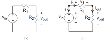
Resistors connected in such a way that current from one must flow only into another currents in all resistors connected this way have the same magnitude are said to be connected in series. For the two series-connected resistors in the example, the voltage across one resistor equals the ratio of that resistor's value and the sum of resistances times the voltage across the series combination. This concept is so pervasive it has a name: voltage divider.
The input-output relationship for this system, found in this particular case by voltage divider, takes the form of a ratio of the output voltage to the input voltage.
In this way, we express how the components used to build the system affect the input-output relationship. Because this analysis was made with ideal circuit elements, we might expect this relation to break down if the input amplitude is too high (Will the circuit survive if the input changes from 1 volt to one million volts?) or if the source's frequency becomes too high. In any case, this important way of expressing input-output relationships as a ratio of output to input pervades circuit and system theory.
The current i1 is the current flowing out of the voltage source. Because it equals i2, we have that
RESISTORS IN SERIES: The series combination of two resistors acts, as far as the voltage source is concerned, as a single resistor having a value equal to the sum of the two resistances.
This result is the first of several equivalent circuit ideas: In many cases, a complicated circuit when viewed from its terminals (the two places to which you might attach a source) appears to be a single circuit element (at best) or a simple combination of elements at worst. Thus, the equivalent circuit for a series combination of resistors is a single resistor having a resistance equal to the sum of its component resistances.
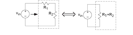
Thus, the circuit the voltage source "feels" (through the current drawn from it) is a single resistor having resistance R1 + R2. Note that in making this equivalent circuit, the output voltage can no longer be defined: The output resistor labeled R2 no longer appears. Thus, this equivalence is made strictly from the voltage source's viewpoint.
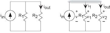
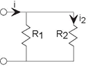
One interesting simple circuit (Figure 3.10) has two resistors connected side-by-side, what we will term a parallel connection, rather than in series. Here, applying KVL reveals that all the voltages are identical: v1 = v and v2 = v. This result typifies parallel connections. To write the KCL equation, note that the top node consists of the entire upper interconnection section. The KCL equation is iin − i1 − i2 =0. Using the v-i relations, we find that
Exercise 3.6.1
Suppose that you replaced the current source in Figure 3.10 by a voltage source. How would iout be related to the source voltage? Based on this result, what purpose does this revised circuit have? This
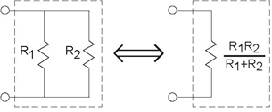
circuit highlights some important properties of parallel circuits. You can easily show that the parallel combination of R1 and R2 has the v-i relation of a resistor having resistance  . A notation for this quantity is ( R1 || R2). As the reciprocal of resistance is conductance (Resistor ), we can say that for a parallel combination of resistors, the equivalent conductance is the sum of the conductances.
Similar to voltage divider for series resistances, we have current divider for parallel resistances. The current through a resistor in parallel with another is the
ratio of the conductance of the first to the sum of the conductances. Thus, for the depicted circuit, . Expressed in terms of resistances, current divider takes the form of the resistance of the other
resistor divided by the sum of resistances:
. Expressed in terms of resistances, current divider takes the form of the resistance of the other
resistor divided by the sum of resistances: 

Suppose we want to pass the output signal into a voltage measurement device, such as an oscilloscope or a voltmeter. In system-theory terms, we want to pass our circuit's output to a sink. For most applications, we can represent these measurement devices as a resistor, with the current passing through it driving the measurement device through some type of display. In circuits, a sink is called a load; thus, we describe a system-theoretic sink as a load resistance RL. Thus, we have a complete system built from a cascade of three systems: a source, a signal processing system (simple as it is), and a sink.
We must analyze afresh how this revised circuit, shown in Figure
3.13, works. Rather than defining eight variables and solving for the current in the load resistor, let's take a hint from other analysis (series rules, parallel rules). Resistors
R2 and RL are in a parallel configuration: The voltages
across each resistor are the same while the currents are not. Because the voltages are the same, we can find the current through each from their v-i relations:  and
and  . Considering the node where all three resistors join, KCL says that the sum of the three currents
must equal zero. Said another way, the current entering the node through R1 must equal the sum of the other two currents leaving
the node. Therefore, i1 = i2 + iL, which means that
. Considering the node where all three resistors join, KCL says that the sum of the three currents
must equal zero. Said another way, the current entering the node through R1 must equal the sum of the other two currents leaving
the node. Therefore, i1 = i2 + iL, which means that 
Let Req denote the equivalent resistance of the parallel combination of R2 and RL. Using R1'sv-i relation, the voltage across it is  . The KVL equation written around the leftmost loop has
vin= v1 + vout ; substituting for v1, we find
. The KVL equation written around the leftmost loop has
vin= v1 + vout ; substituting for v1, we find
or
Thus, we have the input-output relationship for our entire system having the form of voltage divider, but it does not equal the input-output relation of the
circuit without the voltage measurement device. We can not measure voltages reliably unless the measurement device has little effect on what we are trying to measure. We should look more
carefully to determine if any values for the load resistance would lessen its impact on the circuit. Comparing the input-output relations before and after, what we need is  As
As  , the approximation would apply if
  or
or This is the condition we seek:
VOLTAGE MEASUREMENT: Voltage measurement devices must have large resistances compared with that of the resistor across which the voltage is to be measured.
Exercise 3.6.2
Let's be more precise: How much larger would a load resistance need to be to affect the input-output relation by less than 10%? by less than 1%?
Example 3.1
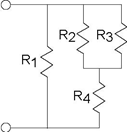
We want to find the total resistance of the example circuit. To apply the series and parallel combination rules, it is best to first determine the circuit's structure: What is in series with
what and what is in parallel with what at both small-and large-scale views. We have R2 in parallel with R3; this combination is in series with R4. This series
combination is in parallel with R1. Note that in determining this structure, we started away from the terminals, and
worked toward them. In most cases, this approach works well; try it first. The total resistance expression mimics the structure:
Such complicated expressions typify circuit "simplifications." A simple check for accuracy is the units: Each component of the numerator should have the same units (here Ω3) as
well as in the denominator (Ω2). The entire expression is to have units of resistance; thus, the ratio of the numerator's and denominator's units should be ohms. Checking units
does not guarantee accuracy, but can catch many errors.
Another valuable lesson emerges from this example concerning the difference between cascading systems and cascading circuits. In system theory, systems can be cascaded without changing the
input-output relation of intermediate systems. In cascading circuits, this ideal is rarely true unless the circuits are so designed.
Design is in the hands of the engineer; he or she must recognize what have come to be known as loading effects. In our simple circuit, you might think that making the resistance RL large enough would do the trick. Because the resistors R1 and R2 can have virtually any value, you can never make the resistance of your voltage
measurement device big enough. Said another way, a circuit cannot be designed in isolation that will work in cascade with all other circuits. Electrical engineers
deal with this situation through the notion of specifications: Under what conditions will the circuit perform as designed? Thus, you will find that oscilloscopes
and voltmeters have their internal resistances clearly stated, enabling you to determine whether the voltage you measure closely equals what was present before they were attached to your
circuit. Furthermore, since our resistor circuit functions as an attenuator, with the attenuation (a fancy word for gains less than one) depending only on the ratio of the two resist or values
 , we can select any values for the two
resistances we want to achieve the desired attenuation. The designer of this circuit must thus specify not only what the attenuation is, but also the resistance values employed so that
integrators people who put systems together from component systems can combine systems together and have a chance of the combination working.
, we can select any values for the two
resistances we want to achieve the desired attenuation. The designer of this circuit must thus specify not only what the attenuation is, but also the resistance values employed so that
integrators people who put systems together from component systems can combine systems together and have a chance of the combination working.
Figure 3.15 summarizes the series and parallel combination results. These results are easy to remember and very useful. Keep in mind that for series combinations, voltage and resistance are the key quantities, while for parallel combinations current and conductance are more important. In series combinations, the currents through each element are the same; in parallel ones, the voltages are the same.
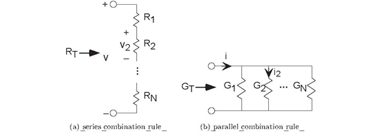
(a)  (b)
(b)
Exercise 3.6.3
Contrast a series combination of resistors with a parallel one. Which variable (voltage or current) is the same for each and which differs? What are the equivalent resistances? When resistors are placed in series, is the equivalent resistance bigger, in between, or smaller than the component resistances? What is this relationship for a parallel combination?
- 5314 reads
