


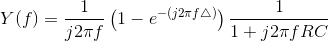
When we apply a periodic input to a linear, time-invariant system, the output is periodic and has Fourier series coefficients equal to the product of the system's frequency response and the input's Fourier coefficients (Filtering Periodic Signals (4.27)). The way we derived the spectrum of non-periodic signal from periodic ones makes it clear that the same kind of result works when the input is not periodic: If x (t) serves as the input to a linear, time-invariant system having frequency response H (f), the spectrum of the output isX (f) H (f).
Example 4.6
Let's use this frequency-domain input-output relationship for linear, time-invariant systems to find a formula for the RC-circuit's response to a pulse
input. We have expressions for the input's spectrum and the system's frequency response.
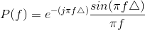
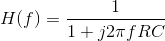
Thus, the output's Fourier transform equals
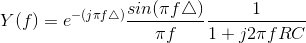
You won't find this Fourier transform in our table, and the required integral is difficult to evaluate as the expression stands. This situation requires cleverness and an understanding of the
Fourier transform's properties. In particular, recall Euler's relation for the sinusoidal term and note the fact that multiplication by a complex exponential in the frequency domain amounts
to a time delay. Let's momentarily make the expression for Y (f) more complicated.
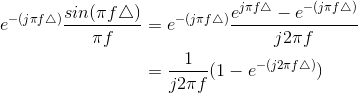
Consequently,
The table of Fourier transform properties (Figure 4.13) suggests thinking about this expression as a product of terms.
- Multiplication by
 means integration.
- Multiplication by the complex exponential e−(j2πfΔ) means delay by Δ seconds in the time domain.
- The term 1 − e−(j2πfΔ) means, in the time domain, subtract the time-delayed signal from its original.
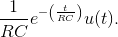
- The inverse transform of the frequency response is
We can translate each of these frequency-domain products into time-domain operations in any order we like because the order in which multiplications occur doesn't
affect the result. Let's start with the product of  (integration in the
time domain) and the transfer function:
(integration in the
time domain) and the transfer function:
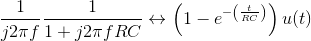
The middle term in the expression for Y (f) consists of the difference of two terms: the constant 1 and the complex exponential e. Because of the Fourier transform's linearity, we simply subtract the results.

Note that in delaying the signal how we carefully included the unit step. The second term in this result does not begin until t =Δ. Thus, the waveforms shown in the
Filtering Periodic Signals (Figure 4.10: Filtering a periodic signal) example mentioned above are exponentials. We say that the time constant of an exponentially
decaying signal equals the time it takes to decrease by  of its original
value. Thus, the time-constant of the rising and falling portions of the output equal the product of the circuit's resistance and capacitance.
of its original
value. Thus, the time-constant of the rising and falling portions of the output equal the product of the circuit's resistance and capacitance.
Exercise 4.9.1
Derive the filter’s output by considering the terms in (4.41) in the order given. Integrate last rather than first. You should get the same answer.
In this example, we used the table extensively to find the inverse Fourier transform, relying mostly on what multiplication by certain factors, like  and
and  , meant. We essentially treated multiplication by these factors as if they were transfer functions of some fictitious
circuit. The transfer function
, meant. We essentially treated multiplication by these factors as if they were transfer functions of some fictitious
circuit. The transfer function  corresponded to a circuit that
integrated, and
corresponded to a circuit that
integrated, and  to one that
delayed. We even implicitly interpreted.
to one that
delayed. We even implicitly interpreted.
the circuit's transfer function as the input's spectrum! This approach to finding inverse transforms breaking down a complicated expression into products and sums of simple components is the engineer's way of breaking down the problem into several subproblems that are much easier to solve and then gluing the results together. Along the way we may make the system serve as the input, but in the rule Y (f)= X (f) H (f), which term is the input and which is the transfer function is merely a notational matter (we labeled one factor with an X and the other with an H).
- 4353 reads
