


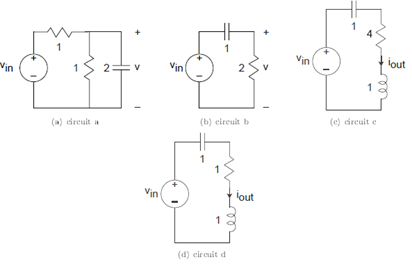
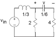
Problem 3.1: Simple Circuit Analysis
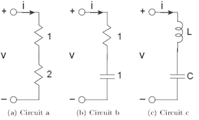
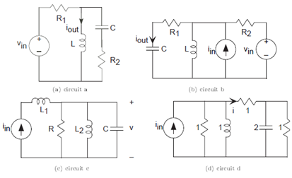
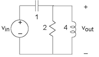
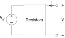
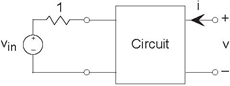
For each circuit shown in Figure 3.52, the current i equals cos (2πt).
- What is the voltage across each element and what is the voltage v in each case?
- For the last circuit, are there element values that make the voltage v equal zero for all time? If so, what element values work?
- Again, for the last circuit, if zero voltage were possible, what circuit element could substitute for the capacitor-inductor series combination that would yield the same voltage?
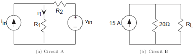
Problem 3.2: Solving Simple Circuits
- Write the set of equations that govern Circuit A's (Figure 3.53) behavior.
- Solve these equations for i1: In other words, express this current in terms of element and source values by eliminating non-source voltages and currents.
- For Circuit B, find the value for RL that results in a current of 5 A passing through it.
- What is the power dissipated by the load resistor RL in this case?
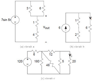
Problem 3.3: Equivalent Resistance
For each of the following circuits (Figure 3.54), find
the equivalent resistance using series and parallel combination rules.
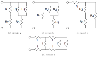
Calculate the conductance seen at the terminals for circuit (c) in terms of each element's conductance. Compare this equivalent conductance formula with the equivalent resistance formula you found for circuit (b). How is the circuit (c) derived from circuit (b)?
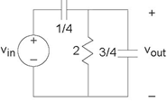
Problem 3.4: Superposition Principle
One of the most important consequences of circuit laws is the Superposition Principle: The current or voltage defined for any element equals the sum of the
currents or voltages produced in the element by the independent sources. This Principle has important consequences in simplifying the calculation of circuit variables in multiple source
circuits.
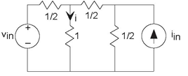
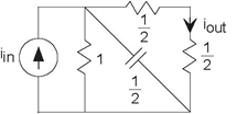
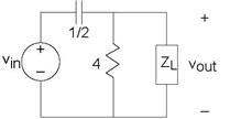
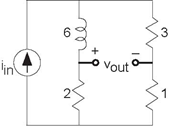
- For the depicted circuit (Figure 3.55), find the indicated current using any technique you like (you should use the simplest).
- You should have found that the current i is a linear combination of the two source values:i = C1vin +C2iin. This result means that we can think of the current as a superposition of two components, each of which is due to a source. We can find each component by setting the other sources to zero. Thus, to find the voltage source component, you can set the current source to zero (an open circuit) and use the usual tricks. To find the current source component, you would set the voltage source to zero (a short circuit) and find the resulting current. Calculate the total current i using the Superposition Principle. Is applying the Superposition Principle easier than the technique you used in part (1)?
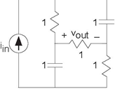
Problem 3.5: Current and Voltage Divider
Use current or voltage divider rules to calculate the indicated circuit variables in Figure 3.56.
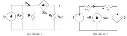
Problem 3.6: Thevenin and Mayer-Norton Equivalents
Find the Thevenin and Mayer-Norton equivalent circuits for the following circuits (Figure 3.57).
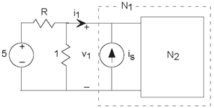
Problem 3.7: Detective Work
In the depicted circuit (Figure 3.58), the circuit N1 has the v-i relation v1 =3i1 +7 when is =2.
- Find the Thevenin equivalent circuit for circuit N2.
- With is =2, determine R such that i1 = −1.
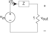
Problem 3.8: Bridge Circuits
Circuits having the form of Figure 3.59 are termed
bridge circuits.
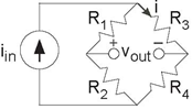
- What resistance does the current source see when nothing is connected to the output terminals?
- What resistor values, if any, will result in a zero voltage for vout?
- Assume R1 = 1Ω, R2 = 2Ω, R3 = 2Ω and R4 = 4Ω. Find the current i when the current source iin is Im ((4+2j) ej2π20t . Express your answer as a sinusoid.
Problem 3.9: Cartesian to Polar Conversion
Convert the following expressions into polar form. Plot their location in the complex plane.
Problem 3.10: The Complex Plane
The complex variable z is related to the real variable u according to 
- Sketch the contour of values z takes on in the complex plane.
- What are the maximum and minimum values attainable by |z|?
- Sketch the contour the rational function
 traces in the complex
plane.
traces in the complex
plane.
Problem 3.11: Cool Curves
In the following expressions, the variable x runs from zero to infinity. What geometric shapes do the following trace in the complex plane?
Problem 3.12: Trigonometric Identities and Complex Exponentials
Show the following trigonometric identities using complex exponentials. In many cases, they were derived using this approach.
Figure 3.61Problem 3.13: Transfer Functions
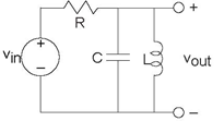
Find the transfer function relating the complex amplitudes of the indicated variable and the source shown in Figure 3.60. Plot the magnitude and phase of the transfer function.
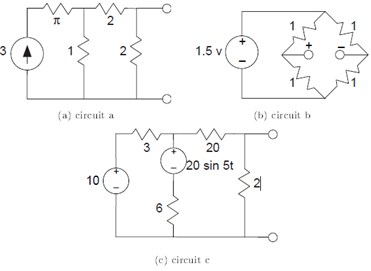
Problem 3.14: Using Impedances
Find the differential equation relating the indicated variable to the source(s) using impedances for each circuit shown in
Problem 3.15: Measurement Chaos
The following simple circuit (Figure 3.62) was
constructed but the signal measurements were made haphazardly. When the source was sin (2πf0t), the current i
(t) equaled  and the voltage
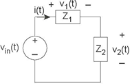
- What is the voltage v1 (t)?
- Find the impedances Z1 and Z2.
- Construct these impedances from elementary circuit elements.
Problem 3.16: Transfer Functions
In the following circuit (Figure 3.63), the voltage
source equals 
- Find the transfer function between the source and the indicated output voltage.
- For the given source, find the output voltage.
Problem 3.17: A Simple Circuit
You are given this simple circuit (Figure 3.64).
- What is the transfer function between the source and the indicated output current?
- If the output current is measured to be cos (2t), what was the source?
Problem 3.18: Circuit Design
- Find the transfer function between the input and the output voltages for the circuits shown in Figure 3.65.
- At what frequency does the transfer function have a phase shift of zero? What is the circuit's gain at this frequency?
- Specifications demand that this circuit have an output impedance (its equivalent impedance) less than 8Ω for frequencies above 1 kHz, the frequency at which the transfer function is maximum. Find element values that satisfy this criterion.
Problem 3.19: Equivalent Circuits and Power
Suppose we have an arbitrary circuit of resistors that we collapse into an equivalent resistor using the series and parallel rules. Is the power dissipated by the equivalent resistor equal to the sum of the powers dissipated by the actual resistors comprising the circuit? Let's start with simple cases and build up to a complete proof.
- Suppose resistors R1 and R2 are connected in parallel. Show that the power dissipated by R1 I R1 equals the sum of the powers dissipated by the component resistors.
- Now suppose R1 and R2 are connected in series. Show the same result for this combination.
- Use these two results to prove the general result we seek.
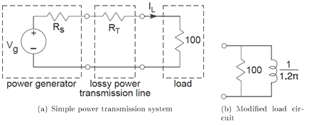
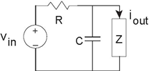
Problem 3.20: Power Transmission
The network shown in the figure represents a simple power transmission system. The generator produces 60 Hz and is modeled by a simple Thevenin equivalent. The transmission line consists of a long length of copper wire and can be accurately described as a 50Ω resistor.
- Determine the load current RL and the average power the generator must produce so that the load receives 1,000 watts of average power. Why does the generator need to generate more than 1,000 watts of average power to meet this requirement?
- Suppose the load is changed to that shown in the second figure. Now how much power must the generator produce to meet the same power requirement? Why is it more than it had to produce to meet the requirement for the resistive load?
- The load can be compensated to have a unity power factor (see exercise (Exercise 3.11.2)) so that the voltage and current are in phase for maximum power efficiency. The compensation technique is to place a circuit in parallel to the load circuit. What element works and what is its value?
- With this compensated circuit, how much power must the generator produce to deliver 1,000 average power to the load?
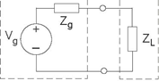
Problem 3.21: Optimal Power Transmission
The following figure (ds) shows a general model for power transmission. The power generator is represented by a Thevinin equivalent and the load by a simple impedance. In most applications, the source components are fixed while there is some latitude in choosing the load.
- Suppose we wanted the maximize "voltage transmission:" make the voltage across the load as large as possible. What choice of load impedance creates the largest load voltage? What is the largest load voltage?
- If we wanted the maximum current to pass through the load, what would we choose the load impedance to be? What is this largest current?
- What choice for the load impedance maximizes the average power dissipated in the load? What is most power the generator can deliver?
Problem 3.22: Big is Beautiful
Sammy wants to choose speakers that produce very loud music. He has an amplifier and notices that the speaker terminals are labeled "8Ω source."
- What does this mean in terms of the amplifier’s equivalent circuit?
- Any speaker Sammy attaches to the terminals can be well-modeled as a resistor. Choosing a speaker amounts to choosing the values for the resistor. What choice would maximize the voltage across the speakers?
- Sammy decides that maximizing the power delivered to the speaker might be a better choice. What values for the speaker resistor should be chosen to maximize the power delivered to the speaker?
Problem 3.23: Sharing a Channel
Two transmitter-receiver pairs want to share the same digital communications channel. The transmitter signals will be added together by the channel. Receiver design is greatly simplified if
first we remove the unwanted transmission (as much as possible). Each transmitter signal has the form
where the amplitude is either zero or A and each transmitter uses its own frequency fi. Each frequency is harmonically related to the bit interval duration T, where the transmitter 1 uses the frequency  . The datarate is 10Mbps.
- Draw a block diagram that expresses this communication scenario.
- Find circuits that the receivers could employ to separate unwanted transmissions. Assume the received signal is a voltage and the output is to be a voltage as well.
- Find the second transmitter's frequency so that the receivers can suppress the unwanted transmission by at least a factor of ten.
Problem 3.24: Circuit Detective Work
In the lab, the open-circuit voltage measured across an unknown circuit's terminals equals sin (t). When a 1Ω resistor is place across the terminals, a
voltage of 
- What is the Thevenin equivalent circuit?
- What voltage will appear if we place a 1 F capacitor across the terminals?
Problem 3.25: Mystery Circuit
We want to determine as much as we can about the circuit lurking in the impenetrable box shown in Figure 3.68. A voltage source vin =2 V has been attached to
the left-hand terminals, leaving the right terminals for tests and measurements.
- Sammy measures v = 10 V when a 1 Ω resistor is attached to the terminals. Samantha says he is wrong. Who is correct and why?
- When nothing is attached to the right-hand terminals, a voltage of v =1 V is measured. What circuit could produce this output?
- When a current source is attached so that i =2amp, the voltage v is now 3 V. What resistor circuit would be consistent with this and the previous part?
Problem 3.26: More Circuit Detective Work
The left terminal pair of a two terminal-pair circuit is attached to a testing circuit. The test source vin (t) equals sin (t) (Figure 3.69).
We make the following measurements.
- With nothing attached to the terminals on the right, the voltage v (t) equals
 .
.
- When a wire is placed across the terminals on the right, the current i(t) was −(sin(t)).
- What is the impedance "seen" from the terminals on the right?
- Find the voltage v (t) if a current source is attached to the terminals on the right so that i(t) = sin(t).
Problem 3.27: Linear, Time-Invariant Systems
For a system to be completely characterized by a transfer function, it needs not only be linear, but also to be time-invariant. A system is said to be time-invariant if delaying the input delays the output by the same amount. Mathematically, if S (x (t)) = y (t), meaning y (t) is the output of a systemS (•) when x (t) is the input, S(•) is the time-invariant if S (x (t − τ)) = y (t − τ) for all delays τ and all inputs x (t). Note that both linear and nonlinear systems have this property. For example, a system that squares its input is time-invariant.
- Show that if a circuit has fixed circuit elements (their values don't change over time), its input-output relationship is time-invariant. Hint: Consider the differential equation that describes a circuit's input-output relationship. What is its general form? Examine the derivative(s) of delayed signals.
- Show that impedances cannot characterize time-varying circuit elements (R, L, and C). Consequently, show that linear, time-varying systems do not have a transfer function.
- Determine the linearity and time-invariance of the following. Find the transfer function of the linear, time-invariant (LTI) one(s).
- diode
- y (t)= x (t) sin (2πf0t)
- y (t)= x (t − τ0)
- y (t)= x (t)+ N (t)
Problem 3.28: Long and Sleepless Nights
Sammy went to lab after a long, sleepless night, and constructed the circuit shown in Figure 3.70. He cannot remember what the circuit, represented by the impedance Z, was. Clearly, this forgotten circuit is important as the output is the current passing through it.
- What is the Thevenin equivalent circuit seen by the impedance?
- In searching his notes, Sammy fnds that the circuit is to realize the transfer function
Find the impedance Z as well as values for the other circuit elements.
Problem 3.29: A Testing Circuit
The simple circuit here (Figure 3.71) was given on a
test.

the current
- What is voltage vout (t)?
- What is the impedance Z at the frequency of the source?
Problem 3.30: Black-Box Circuit
You are given a circuit (Figure 3.72) that has two
terminals for attaching circuit elements.
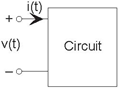
When you attach a voltage source equaling sin (t) to the terminals, the current through the source equals  When no source is attached (open-circuited terminals), the voltage across the terminals has the form Asin (4t + φ).
- What will the terminal current be when you replace the source by a short circuit?
- If you were to build a circuit that was identical (from the viewpoint of the terminals) to the given one, what would your circuit be?
- For your circuit, what are A and φ?
Problem 3.31: Solving a Mystery Circuit
Sammy must determine as much as he can about a mystery circuit by attaching elements to the terminal and measuring the resulting voltage. When he attaches a 1Ω resistor to the circuit's
terminals, he measures the voltage across the terminals to be 3sin (t). When he attaches a 1F capacitor across the terminals, the voltage is now 
- What voltage should he measure when he attaches nothing to the mystery circuit?
- What voltage should Sammy measure if he doubled the size of the capacitor to 2 F and attached it to the circuit?
Problem 3.32: Find the Load Impedance
The depicted circuit (Figure 3.73) has a transfer
function between the output voltage and the source equal to 
- Sketch the magnitude and phase of the transfer function.
- At what frequency does the phase equal π 2 ?
- Find a circuit that corresponds to this load impedance. Is your answer unique? If so, show it to be so; if not, give another example.
Problem 3.33: Analog "Hum" Rejection
"Hum" refers to corruption from wall socket power that frequently sneaks into circuits. "Hum" gets its name because it sounds like a persistent humming sound. We want to find a circuit that will remove hum from any signal. A Rice engineer suggests using a simple voltage divider circuit (Figure 3.74) consisting of two series impedances.
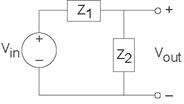
- The impedance Z1 is a resistor. The Rice engineer must decide between two circuits (Figure 3.75) for the impedance Z2. Which of these will work?
- b) Picking one circuit that works, choose circuit element values that will remove hum.
- c) Sketch the magnitude of the resulting frequency response.
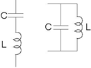 Figure 3.75 Analog "Hum" Rejection 2
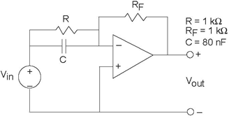
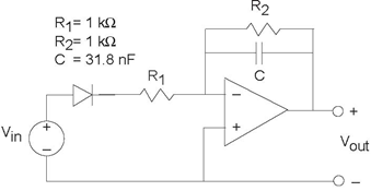
Problem3.34: An Interesting Circuit
- For the circuit shown in Figure 3.76, find the transfer function.
- What is the output voltage when the input has the form iin = 5sin (2000πt)?
Problem 3.35: A Simple Circuit
You are given the depicted circuit (Figure 3.77).
- What is the transfer function between the source and the output voltage?
- What will the voltage be when the source equals sin (t)?
- Many function generators produce a constant offset in addition to a sinusoid. If the source equals 1 + sin(t), what is the output voltage?
Problem 3.36: An Interesting and Useful Circuit
The depicted circuit (Figure 3.78) has interesting properties, which are exploited in high-performance oscilloscopes.
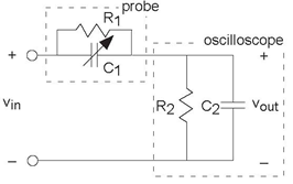
The portion of the circuit labeled "Oscilloscope" represents the scope's input impedance. R2 = 1MΩ and C2 = 30pF (note the label under the channel 1 input in the lab's oscilloscopes). A probe is a device to attach an oscilloscope to a circuit, and it has the indicated circuit inside it.
- Suppose for a moment that the probe is merely a wire and that the oscilloscope is attached to a circuit that has a resistive Thevenin equivalent impedance. What would be the effect of the oscilloscope's input impedance on measured voltages?
- Using the node method, find the transfer function relating the indicated voltage to the source when the probe is used.
- Plot the magnitude and phase of this transfer function when R1 = 9MΩ and C1 = 2pF.
- For a particular relationship among the element values, the transfer function is quite simple. Find that relationship and describe what is so special about it.
- The arrow through C1 indicates that its value can be varied. Select the value for this capacitor to make the special relationship valid. What is the impedance seen by the circuit being measured for this special value?
Problem 3.37: A Circuit Problem
You are given the depicted circuit (Figure 3.79).
- Find the differential equation relating the output voltage to the source.
- What is the impedance "seen" by the capacitor?
Problem 3.38: Analog Computers
Because the differential equations arising in circuits resemble those that describe mechanical motion, we can use circuit models to describe mechanical systems. An ELEC 241 student wants to understand the suspension system on his car. Without a suspension, the car's body moves in concert with the bumps in the raod. A well-designed suspension system will smooth out bumpy roads, reducing the car's vertical motion. If the bumps are very gradual (think of a hill as a large but very gradual bump), the car's vertical motion should follow that of the road. The student wants to find a simple circuit that will model the car's motion. He is trying to decide between two circuit models (Figure 3.80).
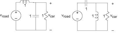
Here, road and car displacements are represented by the voltages Vroad (t) and Vcar (t), respectively.
- Which circuit would you pick? Why?
- For the circuit you picked, what will be the amplitude of the car's motion if the road has a displacement given by Vroad (t) = 1+sin(2t)?
Problem 3.39: Transfer Functions and Circuits
You are given the depicted network (Figure 3.81).
- Find the transfer function between Vin and Vout.
- Sketch the magnitude and phase of your transfer function. Label important frequency, amplitude and phase values.
- Find vout (t) when
Problem 3.40: Fun in the Lab
You are given an unopenable box that has two terminals sticking out. You assume the box contains a circuit. You measure the voltage  across the terminals when nothing is connected to them and the current
  when you place a wire across the terminals.
Problem 3.41: Dependent Sources
Find the voltage Vout in each of the depicted circuits (Figure 3.82).
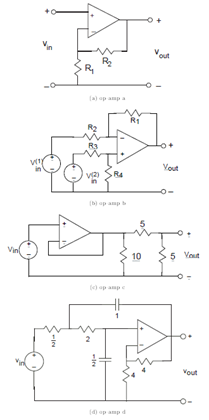
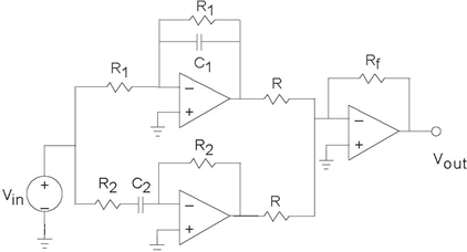
Problem 3.42: Operational Amplifers
Find the transfer function between the source voltage(s) and the indicated output voltage for the circuits shown in Figure 3.83.
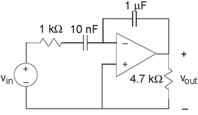
Problem 3.43: Op-Amp Circuit
The following circuit (Figure 3.84) is claimed to serve a
useful purpose.
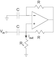
- What is the transfer function relating the complex amplitude of the output signal, the current Iout, to the complex amplitude of the input, the voltage Vin?
- What equivalent circuit does the load resistor RL see?
-
Find the output current when
 .
.
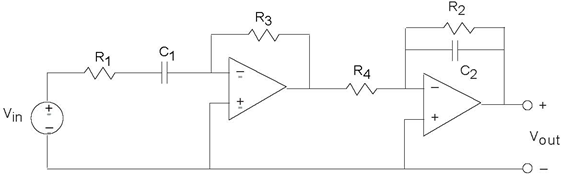
Problem 3.44: Why Op-Amps are Useful
The circuit (Figure 3.85) of a cascade of op-amp
circuits illustrate the reason why op-amp realizations of transfer functions are so useful.
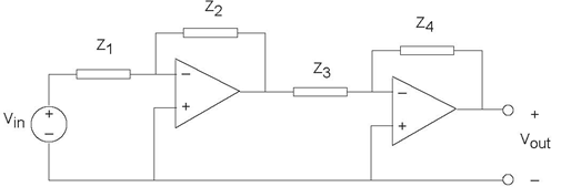
- Find the transfer function relating the complex amplitude of the voltage Vout (t) to the source. Show that this transfer function equals the product of each stage's transfer function.
- What is the load impedance appearing across the first op-amp's output?
- Figure 3.84 illustrates that sometimes "designs" can go wrong. Find the transfer function for this op-amp circuit (Figure 3.86), and then show that it can't work! Why can't it?
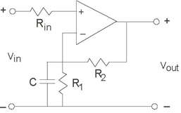
Problem 3.45: Operational Amplifiers
Consider the depicted circuit (Figure 3.87).
- Find the transfer function relating the voltage Vout (t) to the source.
- In particular, R1 = 530Ω, C1 =1µF, R2 =5.3kΩ, C2 =0.01µF, and R3 = R4 =5.3kΩ. Characterize the resulting transfer function and determine what use this circuit might have.
Problem 3.46: Designing a Bandpass Filter
We want to design a bandpass filter that has transfer the function
Here, fl is the cutoff frequency of the low-frequency edge of the passband and fh is the
cutoff frequency of the high-frequency edge. We want fl = 1kH z and fh = 10kHz.
- Plot the magnitude and phase of this frequency response. Label important amplitude and phase values and the frequencies at which they occur.
- Design a bandpass filter that meets these specifications. Specify component values.
Problem 3.47: Pre-emphasis or De-emphasis?
In audio applications, prior to analog-to-digital conversion signals are passed through what is known as a pre-emphasis circuit that leaves the low frequencies
alone but provides increasing gain at increasingly higher frequencies beyond some frequency f0. De-emphasis
circuits do the opposite and are applied after digital-to-analog conversion. After pre-emphasis, digitization, conversion back to analog and de-emphasis, the signal's spectrum should
be what it was.
The op-amp circuit here (Figure 3.88) has been
designed for pre-emphasis or de-emphasis (Samantha can't recall which).
- Is this a pre-emphasis or de-emphasis circuit? Find the frequency f0 that defines the transition from low to high frequencies.
- What is the circuit's output when the input voltage is sin (2πft), with f = 4kHz?
- What circuit could perform the opposite function to your answer for the first part?
Problem 3.48: Active Filter
Find the transfer function of the depicted active filter (Figure
3.89).
Problem 3.49: This is a filter?
You are given a circuit (Figure 3.90).
- What is this circuit's transfer function? Plot the magnitude and phase.
- If the input signal is the sinusoid sin (2πf0t), what will the output be when f0 is larger than the filter’s "cutoff frequency"?
Problem 3.50: Optical Receivers
In your optical telephone, the receiver circuit had the form shown (Figure 3.91).
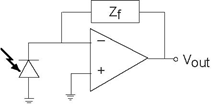
This circuit served as a transducer, converting light energy into a voltage vout. The photodiode acts as a current source, producing a current proportional to the light intensity falling upon it. As is often the case in this crucial stage, the signals are small and noise can be a problem. Thus, the op-amp stage serves to boost the signal and to filter out-of-band noise.
- Find the transfer function relating light intensity to vout.
- What should the circuit realizing the feedback impedance Zf be so that the transducer acts as a 5 kHz lowpass filter?
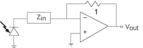
- A clever engineer suggests an alternative circuit (Figure 3.92) to accomplish the same task. Determine whether the idea works or not. If it does, find the impedance Zin that accomplishes the lowpass filtering task. If not, show why it does not work.
Problem 3.51: Reverse Engineering
The depicted circuit (Figure 3.93) has been developed by
the TBBG Electronics design group. They are trying to keep its use secret; we, representing RU Electronics, have discovered the schematic and want to figure out the intended application.
Assume the diode is ideal.
- Assuming the diode is a short-circuit (it has been removed from the circuit), what is the circuit's
- transfer function?
- With the diode in place, what is the circuit's output when the input voltage is sin (2πf0t)?
- What function might this circuit have?
- 11137 reads
