Problem 2.1: Complex Number Arithmetic
Find the real part, imaginary part, the magnitude and angle of the complex numbers given by the following expressions.
Problem 2.2: Discovering Roots
Complex numbers expose all the roots of real (and complex) numbers. For example, there should be two square-roots, three cube-roots, etc. of any number. Find the following roots.
- What are the cube-roots of 27? In other words, what is
 ?
?
- What are the fifth roots of

- What are the fourth roots of one?
Problem 2.3: Cool Exponentials
Simplify the following (cool) expressions.
Problem 2.4: Complex-valued Signals
Complex numbers and phasors play a very important role in electrical engineering. Solving systems for complex exponentials is much easier than for sinusoids, and linear systems analysis is particularly easy.
- Find the phasor representation for each, and re-express each as the real and imaginary parts of a complex exponential. What is the frequency (in Hz) of each? In general, are your answers
unique? If so, prove it; if not, find an alternative answer for the complex exponential representation.
-
- Show that for linear systems having real-valued outputs for real inputs, that when the input is the real part of a complex exponential, the output is the real part of the system's output to the complex exponential (see the below figure).


Problem 2.5:
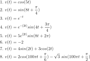
For each of the indicated voltages, write it as the real part of a complex exponential (v (t)= Re (Vest)). Explicitly indicate the
value of the complex amplitude V and the complex frequency s. Represent each complex amplitude as a vector in the V -plane, and indicate the location of the
frequencies in the complex s-plane.

Problem 2.6:
Express each of the following signals (signal a-e) as a linear combination of delayed and weighted step functions and ramps (the integral of a step).


Problem 2.7: Linear, Time-Invariant Systems
When the input to a linear, time-invariant system is the signal x (t), the output is the signal y (t) (The following figure).

- Find and sketch this system's output when the input is the depicted signal (Figure 2.19).
- Find and sketch this system's output when the input is a unit step.

Problem 2.8: Linear Systems
The depicted input (Figure below) x (t) to a linear, time-invariant system yields the output y (t).
↵
- What is the system's output to a unit step input u (t)?
- What will the output be when the input is the depicted square wave in the following figure?

Problem 2.9: Communication Channel
A particularly interesting communication channel can be modeled as a linear, time-invariant system. When the transmitted signal x (t) is a pulse, the
received signal r (t) is as shown (in the following Figure).

- What will be the received signal when the transmitter sends the pulse sequence (Figure 2.23) x1 (t)?
- What will be the received signal when the transmitter sends the pulse signal (the figure below) x2 (t) that has half the duration as the original?

Problem 2.10: Analog Computers
So-called analog computers use circuits to solve mathematical problems, particularly when they involve differential equations. Suppose we are given the following
differential equation to solve.

In this equation,a is a constant.
- When the input is a unit step (x (t)= u (t)), the output is given by y (t)= 1 − eu (t-(at)) u(t) . What is the total energy expended by the input?
- Instead of a unit step, suppose the input is a unit pulse (unit-amplitude, unit-duration) delivered to the circuit at time t = 10. What is the output voltage in this case? Sketch the waveform.
- 5938 reads


