


A circuit connects circuit elements together in a specific configuration designed to transform the source signal (originating from a voltage or current source) into another signal the output that corresponds to the current or voltage defined for a particular circuit element. A simple resistive circuit is shown in Figure 3.6.
This circuit is the electrical embodiment of a system having its input provided by a source system producing vin (t).
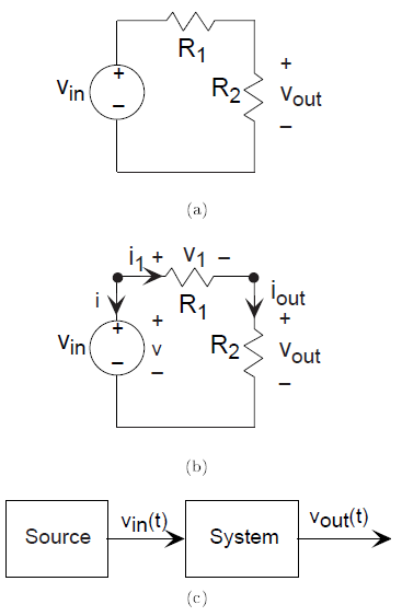
To understand what this circuit accomplishes, we want to determine the voltage across the resistor labeled by its value R2. Recasting this problem mathematically, we need to solve some set of equations so that we relate the output voltage vout to the source voltage. It would be simple a little too simple at this point if we could instantly write down the one equation that relates these two voltages. Until we have more knowledge about how circuits work, we must write a set of equations that allow us to find all the voltages and currents that can be defined for every circuit element. Because we have a three-element circuit, we have a total of six voltages and currents that must be either specified or determined. You can define the directions for positive current flow and positive voltage drop any way you like. Once the values for the voltages and currents are calculated, they may be positive or negative according to your definition. When two people define variables according to their individual preferences, the signs of their variables may not agree, but current flow and voltage drop values for each element will agree. Do recall in defining your Ideal Circuit Elements that the v-i relations for the elements presume that positive current flow is in the same direction as positive voltage drop. Once you define voltages and currents, we need six nonredundant equations to solve for the six unknown voltages and currents. By specifying the source, we have one; this amounts to providing the source's v-i relation. The v-i relations for the resistors give us two more. We are only halfway there; where do we get the other three equations we need?
What we need to solve every circuit problem are mathematical statements that express how the circuit elements are interconnected. Said another way, we need the laws that govern the electrical connection of circuit elements. First of all, the places where circuit elements attach to each other are called nodes. Two nodes are explicitly indicated in Figure 3.6; a third is at the bottom where the voltage source and resistor R2are connected. Electrical engineers tend to draw circuit diagrams schematics in a rectilinear fashion. Thus the long line connecting the bottom of the voltage source with the bottom of the resistor is intended to make the diagram look pretty. This line simply means that the two elements are connected together. Kirchhof's Current Law, one for voltage and one for current, determine what a connection among circuit elements means. These laws are essential to analyzing this and any circuit. They are named for Gustav Kirchhofll , a nineteenth century German physicist.
- 5652 reads
