


We have found that the way to think about circuits is to locate and group parallel and series resistor combinations. Those resistors not involved with variables of interest can be collapsed into a single resistance. This result is known as an equivalent circuit: from the viewpoint of a pair of terminals, a group of resistors functions as a single resistor, the resistance of which can usually be found by applying the parallel and series rules.
This result generalizes to include sources in a very interesting and useful way. Let's consider our simple attenuator circuit (shown in the figure (Figure 3.16) from the viewpoint of the output terminals. We want to find the v-i relation for the output terminal pair, and then find the equivalent circuit for the boxed circuit. Two perform this calculation, use the circuit laws and element relations,
but do not attach anything to the output terminals. We seek the relation between v and i that describes the kind of element that lurks within the dashed box. The result is
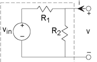
If the source were zero, it could be replaced by a short circuit, which would confirm that the circuit does indeed function as a parallel combination of resistors. However, the source's presence means that the circuit is not well modeled as a resistor.
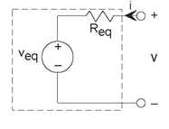
If we consider the simple circuit of Figure 3.17, we find it has the v-i relation at its terminals of
Comparing the two v-i relations, we find that they have the same form. In this case the Thevenin equivalent resistance is
Req = ( R1 || R2 ) and the Thevenin equivalent source has voltage Thus, from viewpoint of the terminals, you cannot
distinguish the two circuits. Because the equivalent circuit has fewer elements, it is easier to analyze and understand than any other alternative.
Thus, from viewpoint of the terminals, you cannot
distinguish the two circuits. Because the equivalent circuit has fewer elements, it is easier to analyze and understand than any other alternative.
For any circuit containing resistors and sources, the v-i relation will be of the form
and the Thevenin equivalent circuit for any such circuit is that of Figure 3.17. This equivalence applies no matter how many sources or resistors may be present in the circuit. In the example (Example 3.2) below, we know the circuit's construction and element values, and derive the equivalent source and resistance. Because Thevenin's theorem applies in general, we should be able to make measurements or calculations only from the terminals to determine the equivalent circuit.
To be more specific, consider the equivalent circuit of this figure (Figure 3.17). Let the terminals be opencircuited, which has the effect of setting the current i to zero. Because no current flows through the resistor, the voltage across it
is zero (remember, Ohm's Law says that v = Ri). Consequently, by applying KVL we have that the so-called
open-circuit voltage voc equals the Thevenin equivalent voltage. Now consider the situation when we set the terminal voltage to zero (short-circuit it) and measure
the resulting current. Referring to the equivalent circuit, the source voltage now appears entirely across the resistor, leaving the short-circuit current to be . From this property, we can determine the
equivalent resistance.
. From this property, we can determine the
equivalent resistance.

Exercise 3.7.1
Use the open/short-circuit approach to derive the Thevenin equivalent of the circuit shown in Figure 3.18.

Example 3.2
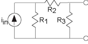
For the circuit depicted in Figure 3.19, let's derive its
Thevenin equivalent two different ways. Starting with the open/short-circuit approach, let's first find the open-circuit voltage voc. We have a current divider relationship as R1 is in
parallel with the series combination of R2 and R3.Thus,  When we short-circuit the terminals, no voltage appears across R3, and thus no current flows through it. In short, R3 does not affect the
short-circuit current, and can be eliminated. We again have a current divider relationship:
When we short-circuit the terminals, no voltage appears across R3, and thus no current flows through it. In short, R3 does not affect the
short-circuit current, and can be eliminated. We again have a current divider relationship:  . Thus, the Thevenin equivalent resistance is
To verify, let's find the equivalent resistance by reaching inside the circuit and setting the current source to zero. Because the current is now zero, we can replace the current source by an open circuit. From the viewpoint of the terminals, resistor R3 is now in parallel with the series combination of R1 and R2. Thus, Req = ( R3 || R1 + R2), and we obtain the same result.
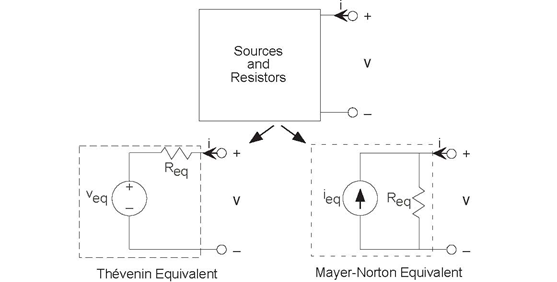
As you might expect, equivalent circuits come in two forms: the voltage-source oriented Thevenin equivalentl5 and the current-source oriented Mayer-Norton equivalent (Figure 3.20). To derive the latter, the v-i relation for the Thevenin equivalent can be written as
or
where  is the Mayer-Norton equivalent source. The
Mayer-Norton equivalent shown in Figure 3.20 can be easily shown to have this
v-i relation. Note that both variations have the same equivalent resistance. The short-circuit current equals the negative of the Mayer-Norton equivalent
source.
is the Mayer-Norton equivalent source. The
Mayer-Norton equivalent shown in Figure 3.20 can be easily shown to have this
v-i relation. Note that both variations have the same equivalent resistance. The short-circuit current equals the negative of the Mayer-Norton equivalent
source.
Exercise 3.7.2
Find the Mayer-Norton equivalent circuit for the circuit below.

Equivalent circuits can be used in two basic ways. The first is to simplify the analysis of a complicated circuit by realizing the any portion of a circuit can be described by either a
Thevenin or Mayer-Norton equivalent. Which one is used depends on whether what is attached to the terminals is a series confguration (making the Thevenin equivalent the best) or a parallel
one (making Mayer-Norton the best).
Another application is modeling. When we buy a fashlight battery, either equivalent circuit can accurately describe it. These models help us understand the limitations of a battery. Since
batteries are labeled with a voltage specifcation, they should serve as voltage sources and the Thevenin equivalent serves as the natural choice. If a load resistance RL is placed across its terminals, the voltage output can be found using voltage divider :  If we have a load resistance much larger than the battery's
equivalent resistance, then, to a good approximation, the battery does serve as a voltage source. If the load resistance is much smaller, we certainly don't have a voltage source (the output
voltage depends directly on the load resistance). Consider now the Mayer-Norton equivalent; the current through the load resistance is given by current divider, and equals
If we have a load resistance much larger than the battery's
equivalent resistance, then, to a good approximation, the battery does serve as a voltage source. If the load resistance is much smaller, we certainly don't have a voltage source (the output
voltage depends directly on the load resistance). Consider now the Mayer-Norton equivalent; the current through the load resistance is given by current divider, and equals  For a current that does not vary with the
load resistance, this resistance should be much smaller than the equivalent resistance. If the load resistance is comparable to the equivalent resistance, the battery serves neither as a voltage source or a current course. Thus, when you buy a battery, you get a voltage source if its equivalent resistance is much smaller than the equivalent resistance of the circuit to which you attach it. On the other hand, if you attach it to a circuit having a small equivalent resistance, you bought
a current source.
For a current that does not vary with the
load resistance, this resistance should be much smaller than the equivalent resistance. If the load resistance is comparable to the equivalent resistance, the battery serves neither as a voltage source or a current course. Thus, when you buy a battery, you get a voltage source if its equivalent resistance is much smaller than the equivalent resistance of the circuit to which you attach it. On the other hand, if you attach it to a circuit having a small equivalent resistance, you bought
a current source.
LEON CHARLES THEVENIN: He was an engineer with France's Postes, Telegraphe et Telephone. In 1883, he published (twice!) a proof of what is now called the Thevenin equivalent while developing ways of teaching electrical engineering concepts at the Ecole Polytechnique. He did not realize that the same result had been published by Hermann Helmholtz, the renowned nineteenth century physicist, thiry years earlier.
HANS FERDINAND MAYER: After earning his doctorate in physics in 1920, he turned to communications engineering when he joined Siemens & Halske in 1922. In 1926, he published in a German technical journal the Mayer-Norton equivalent. During his interesting career, he rose to lead Siemen's Central Laboratory in 1936, surruptiously leaked to the British all he knew of German warfare capabilities a month after the Nazis invaded Poland, was arrested by the Gestapo in 1943 for listening to BBC radio broadcasts, spent two years in Nazi concentration camps, and went to the United States for four years working for the Air Force and Cornell University before returning to Siemens in 1950. He rose to a position on Siemen's Board of Directors before retiring.
EDWARD L. NORTON: Edward Norton was an electrical engineer who worked at Bell Laboratory from its inception in 1922. In the same month when Mayer's paper appeared, Norton wrote in an internal technical memorandum a paragraph describing the current-source equivalent. No evidence suggests Norton knew of Mayer's publication.
- 瀏覽次數:6412
