


The receiver interested in the transmitted bit stream must perform two tasks when received waveform r (t) begins.
- It must determine when bit boundaries occur: The receiver needs to synchronize with the transmitted signal. Because transmitter and receiver are designed in concert, both use the same value for the bit interval T. Synchronization can occur because the transmitter begins sending with a reference bit sequence, known as the preamble. This reference bit sequence is usually the alternating sequence as shown in the square wave example and in the FSK example (Figure 6.13). The receiver knows what the preamble bit sequence is and uses it to determine when bit boundaries occur. This procedure amounts to what in digital hardware as self-clockingsignaling: The receiver of a bit stream must derive the clock when bit boundaries occur from its input signal. Because the receiver usually does not determine which bit was sent until synchronization occurs, it does not know when during the preamble it obtained synchronization. The transmitter signals the end of the preamble by switching to a second bit sequence. The second preamble phase informs the receiver that data bits are about to come and that the preamble is almost over.
- Once synchronized and data bits are transmitted, the receiver must then determine every T seconds what bit was transmitted during the previous bit interval. We focus on this aspect of the digital receiver because this strategy is also used in synchronization. The receiver for digital communication is known as a matched filter. Optimal receiver structure
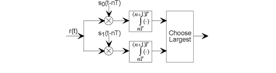
The optimal receiver structure for digital communication faced with additive white noise channels is the depicted matched filter.
This receiver, shown in Figure 6.14 (Optimal
receiver structure), multiplies the received signal by each of the possible members of the transmitter signal set, integrates the product over the bit interval, and compares the results.
Whichever path through the receiver yields the largest value corresponds to the receiver's decision as to what bit was sent during the previous bit interval. For the next bit interval, the
multiplication and integration begins again, with the next bit decision made at the end of the bit interval. Mathematically, the received value of b (n),
which we label  is given by
(6.42)
You may not have seen the  notation before. maxi{i, ·} yields the maximum value of its argument with respect to the index
 equals the value of the index that yields the maximum. Note that
the precise numerical value of the integrator's output does not matter; what does matter is its value relative to the other integrator's output.
equals the value of the index that yields the maximum. Note that
the precise numerical value of the integrator's output does not matter; what does matter is its value relative to the other integrator's output.
Let's assume a perfect channel for the moment: The received signal equals the transmitted one. If bit 0 were sent using the baseband BPSK signal set, the integrator outputs would be
(6.43)
If bit 1 were sent,
(6.44)
Exercise 6.16.1
Can you develop a receiver for BPSK signal sets that requires only one multiplier-integrator combination?
Exercise 6.16.2
What is the corresponding result when the amplitude-modulated BPSK signal set is used? Clearly, this receiver would always choose the bit correctly. Channel attenuation would not affect this correctness; it would only make the values smaller, but all that matters is which is largest.
- 5832 reads
