


A dependent source is either a voltage or current source whose value is proportional to some other voltage or current in the circuit. Thus, there are four different kinds of dependent sources; to describe an op-amp, we need a voltage-dependent voltage source. However, the standard circuit-theoretical model for a transistor contains a current-dependent current source. Dependent sources do not serve as inputs to a circuit like independent sources. They are used to model active circuits: those containing electronic elements. The RLC circuits we have been considering so far are known as passive circuits.
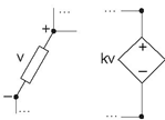
Figure 3.40 shows the circuit symbol for the op-amp and its equivalent circuit in terms of a voltage-dependent voltage source.
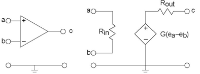
Here, the output voltage equals an amplified version of the difference of node voltages appearing across its inputs. The dependent source model portrays how the op-amp works quite well. As in most active circuit schematics, the power supply is not shown, but must be present for the circuit model to be accurate. Most operational amplifiers require both positive and negative supply voltages for proper operation.
Because dependent sources cannot be described as impedances, and because the dependent variable cannot "disappear" when you apply parallel/series combining rules, circuit simplifications such as current and voltage divider should not be applied in most cases. Analysis of circuits containing dependent sources essentially requires use of formal methods, like the node method (Section 3.15). Using the node method for such circuits is not difficult, with node voltages defined across the source treated as if they were known (as with independent sources). Consider the circuit shown on the top in Figure 3.41.
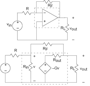
Note that the op-amp is placed in the circuit "upside-down," with its inverting input at the top and serving as the only input. As we explore op-amps in more detail in the next section, this configuration will appear again and again and its usefulness demonstrated. To determine how the output voltage is related to the input voltage, we apply the node method. Only two node voltages v and vout need be defined; the remaining nodes are across sources or serve as the reference. The node equations are
Note that no special considerations were used in applying the node method to this dependent-source circuit. Solving these to learn how vout relates to vin yields

This expression represents the general input-output relation for this circuit, known as the standard feedback configuration. Once we learn more about Operational Amplifiers, in particular what its typical element values are, the expression will simplify greatly. Do note that the units check, and that the parameter G of the dependent source is a dimensionless gain.
- 3461 reads
