


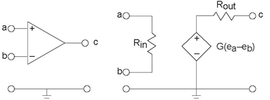
Op-amps not only have the circuit model shown in Figure 3.42, but their element values are very special.
- The input resistance, Rin, is typically large, on the order of 1 MΩ.
- The output resistance, Rout, is small, usually less than 100 Ω.
- The voltage gain, G, is large, exceeding 105.
The large gain catches the eye; it suggests that an op-amp could turn a 1 mV input signal into a 100 V one. If you were to build such a circuit attaching a voltage source to node a, attaching node b to the reference, and looking at the output you would be disappointed. In dealing with electronic components, you cannot forget the unrepresented but needed power supply.
UNMODELED LIMITATIONS IMPOSED BY POWER SUPPLIES: It is impossible for electronic components to yield voltages that exceed those provided by the power supply or for them to yield currents that exceed the power supply's rating.
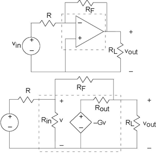
Typical power supply voltages required for op-amp circuits are ± (15V ). Attaching the 1 mv signal not only would fail to produce a 100 V signal, the resulting waveform would be severely distorted. While a desirable outcome if you are a rock & roll aficionado, high-quality stereos should not distort signals. Another consideration in designing circuits with op-amps is that these element values are typical: Careful control of the gain can only be obtained by choosing a circuit so that its element values dictate the resulting gain, which must be smaller than that provided by the op-amp.
- 3112 reads
