


The resistor, capacitor, and inductor are linear circuit elements in that their v-i relations are linear in the mathematical sense. Voltage and current sources are (technically) nonlinear devices: stated simply, doubling the current through a voltage source does not double the voltage. A more blatant, and very useful, nonlinear circuit element is the diode (learn more34 ). Its input-output relation has an exponential form.
Here, the quantity q represents the charge of a single electron in coulombs, k is Boltzmann's constant, and
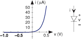
T is the diode's temperature in K. At room temperature, the ratio  The constant I0 is the leakage current, and is usually very small. Viewing this v-i relation in Figure 3.48 (Diode), the nonlinearity becomes obvious. When the voltage is positive, current flows easily through the diode. This situation is known as
forward biasing. When we apply a negative voltage, the current is quite small, and equals I0, known as the leakage or reverse-bias current. A less detailed model for the diode has any positive current flowing through the diode when it is forward biased, and no current when negative biased. Note
that the diode's schematic symbol looks like an arrowhead; the direction of current flow corresponds to the direction the arrowhead points.
The constant I0 is the leakage current, and is usually very small. Viewing this v-i relation in Figure 3.48 (Diode), the nonlinearity becomes obvious. When the voltage is positive, current flows easily through the diode. This situation is known as
forward biasing. When we apply a negative voltage, the current is quite small, and equals I0, known as the leakage or reverse-bias current. A less detailed model for the diode has any positive current flowing through the diode when it is forward biased, and no current when negative biased. Note
that the diode's schematic symbol looks like an arrowhead; the direction of current flow corresponds to the direction the arrowhead points.
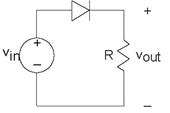
Because of the diode's nonlinear nature, we cannot use impedances nor series/parallel combination rules to analyze circuits containing them. The reliable node method can always be used; it only relies on KVL for its application, and KVL is a statement about voltage drops around a closed path regardless of whether the elements are linear or not. Thus, for this simple circuit we have
This equation cannot be solved in closed form. We must understand what is going on from basic principles, using computational and graphical aids. As an approximation, when vin is positive, current flows through the diode so long as the voltage vout is smaller than vin (so the diode is forward biased). If the source is negative or vout "tries" to be bigger than vin, the diode is reverse-biased, and the reverse-bias current flows through the diode. Thus, at this level of analysis, positive input voltages result in positive output voltages with negative ones resulting in vout = −(RI0).
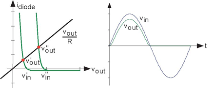
We need to detail the exponential nonlinearity to determine how the circuit distorts the input voltage waveform. We can of course numerically solve Figure 3.50 to determine the output voltage when the input is a sinusoid. To learn more, let's express this equation graphically. We plot each term as a function of vout for various values of the input voltage vin; where they intersect gives us the output voltage. The left side, the current through the output resistor, does not vary itself with vin, and thus we have a fixed straight line. As for the right side, which expresses the diode's v-i relation, the point at which the curve crosses the vout axis gives us the value of vin. Clearly, the two curves will always intersect just once for any value of vin, and for positive vin the intersection occurs at a value for voutsmaller than vin. This reduction is smaller if the straight line has a shallower slope, which corresponds to using a bigger output resistor. For negative vin, the diode is reverse-biased and the output voltage equals − (RI0).
What utility might this simple circuit have? The diode's nonlinearity cannot be escaped here, and the clearly evident distortion must have some practical application if the circuit were to be useful. This circuit, known as a half-wave rectifier, is present in virtually every AM radio twice and each serves very different functions! We'll learn what functions later.
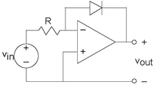
Here is a circuit involving a diode that is actually simpler to analyze than the previous one. We know that the current through the resistor must equal that through the diode. Thus, the diode's current is proportional to the input voltage. As the voltage across the diode is related to the logarithm of its current, we see that the input-output relation is
Clearly, the name logarithmic amplifier is justified for this circuit.
- 2510 reads
