


Especially for wireless channels, like commercial radio and television, but also for wireline systems like cable television, an analog message signal must be modulated: The transmitted signal's spectrum occurs at much higher frequencies than those occupied by the signal.
POINT OF INTEREST: We use analog communication techniques for analog message signals, like music, speech, and television. Transmission and reception of analog signals using analog results in an inherently noisy received signal (assuming the channel adds noise, which it almost certainly does).
The key idea of modulation is to affect the amplitude, frequency or phase of what is known as the carrier sinusoid. Frequency modulation (FM) and less frequently used phase modulation (PM) are not discussed here; we focus on amplitude modulation (AM). The amplitude modulated message signal has the form

(6.29)
where fc is the carrier frequency and Ac the carrier amplitude. Also, the signal's amplitude is assumed to be less than one: |m (t) | < 1. From our previous exposure to amplitude modulation (see the Fourier Transform example (Example 4.5)), we know that the transmitted signal's spectrum occupies the frequency range [fc − W, fc + W ], assuming the signal's bandwidth is W Hz (see the figure (Figure 6.6)). The carrier frequency is usually much larger than the signal's highest frequency: fc » W , which means that the transmitter antenna and carrier frequency are chosen jointly during the design process.
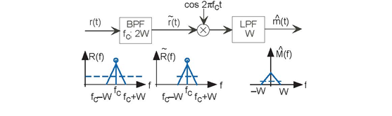
The AM coherent receiver along with the spectra of key signals is shown for the case of a triangular-shaped signal spectrum. The dashed line indicates the white noise level. Note that the filters' characteristics cutoff frequency and center frequency for the bandpass filter must be match to the modulation and message parameters.
Ignoring the attenuation and noise introduced by the channel for the moment, reception of an amplitude modulated signal is quite easy (see Problem 4.20). The so-called coherent receiver multiplies the input signal by a sinusoid and lowpass-filters the result (Figure 6.6).
(6.30)
Because of our trigonometric identities, we know that
(6.31)
At this point, the message signal is multiplied by a constant and a sinusoid at twice the carrier frequency. Multiplication by the constant term returns the message signal to baseband (where we want it to be!) while multiplication by the double-frequency term yields a very high frequency signal. The lowpass filter removes this high-frequency signal, leaving only the baseband signal. Thus, the received signal is
(6.32)
Exercise 6.11.1
This derivation relies solely on the time domain; derive the same result in the frequency domain. You won't need the trigonometric identity with this approach.
Because it is so easy to remove the constant term by electrical means we insert a capacitor in series with the receiver's output we typically ignore it and concentrate on the signal portion of the receiver's output when calculating signal-to-noise ratio.
- 3805 reads
