


The feedback configuration shown in Figure 3.43 is the most common op-amp circuit for obtaining what is known as an inverting amplifier.

provides the exact input-output relationship. In choosing element values with respect to op-amp characteristics, we can simplify the expression dramatically.
- Make the load resistance, RL, much larger than Rout. This situation drops the term from the second factor of (3.27).
- Make the resistor, R, smaller than Rin, which means that the
 term in the third factor is negligible.
With these two design criteria, the expression becomes
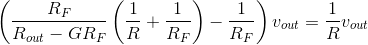
Because the gain is large and the resistance Rout is small, the first term becomes , leaving us with
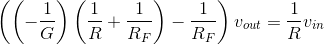
If we select the values of RF and R so that (GR » RF), this factor will no longer depend on the
op-amp's inherent gain, and it will equal  .
.
Under these conditions, we obtain the classic input-output relationship for the op-amp-based inverting amplifier.
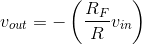
Consequently, the gain provided by our circuit is entirely determined by our choice of the feedback resistor RF and the input resistor R. It is always negative, and can be less than one or greater than one in magnitude. It cannot exceed the op-amp's inherent gain and should not produce such large outputs that distortion results (remember the power supply!). Interestingly, note that this relationship does not depend on the load resistance. This effect occurs because we use load resistances large compared to the op-amp's output resistance. Thus observation means that, if careful, we can place op-amp circuits in cascade, without incurring the effect of succeeding circuits changing the behavior (transfer function) of previous ones; see this problem (Problem 3.44).
- 2293 reads
